We placed air terminals and an air handling unit in our last tutorial. We also created return air and supply air systems.
Now we will continue to work with the model and create the route using Generate Layout tool (Auto-Route creation).
Creating Supply Air Route
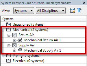
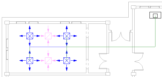
In System Browser, select Mechanical Supply Air 1. If you don’t have System Browser open, press F9 to open it.
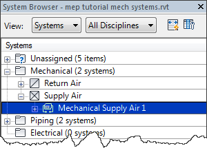
You will see all equipment on the system selected. You will also see a boundary around the system.
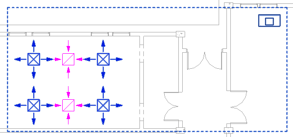
You can also select a system by placing your mouse cursor above an air terminal and press tab until you see the system is highlighted.
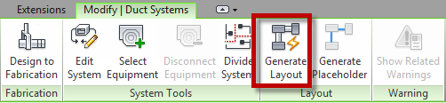
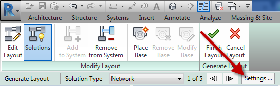
In Revit Ribbon, the Contextual tab you will see Generate Layout button. Click it.
You will see a preview of the route solution. Let’s modify the route settings.
Click Settings on the Options bar.
For the main route set the following:
- Duct Type: Rectangular Duct: Radius Elbows / Tees
- Offset: 3250
For the branch set the following:
- Duct Type: Rectangular Duct: Radius Elbows / Tees
- Offset: 3250
- Flex Duct Type: None
- Max Flex Duct Length: 1800.0
Click OK to close the settings dialog.
Now click the arrow next to Solution Type. In this example, I have five available solutions that I can use. Review all possible solutions.
![]()
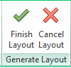
In this tutorial, the first solution looks to be the best option. Click Finish Layout.
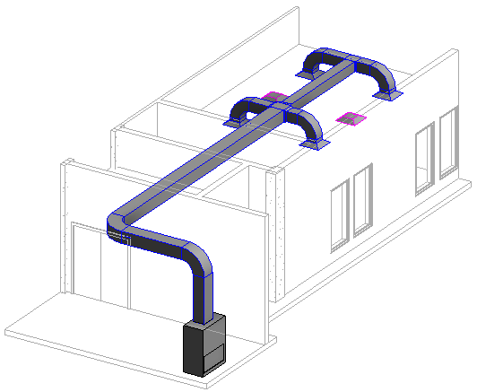
Review the route in 3D.
In many occasions, you might see warning or error when creating route with this method. You can still use the Generate Layout tool and fix the error later. It can be faster and easier than create the route manually. But sometimes it will be easier to create the route manually from beginning.
Change the Duct Height
Let’s modify the route. We will change the duct height because it’s too low. Open 3D view and select the duct shown below.
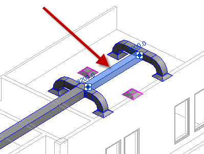
Change the offset value in the options bar to 3500.
![]()
You will see the entire route height is changed.
Change Duct Size
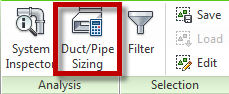
Move your pointer above a duct and press tab until you see all ducts are highlighted. Click your mouse to select it.

On Contextual Ribbon tab> Analysis panel click Duct/Pipe Sizing.
Revit will open the Duct Sizing dialog. Review the available settings. We will not change anything here, but feel free if you want to change the settings.
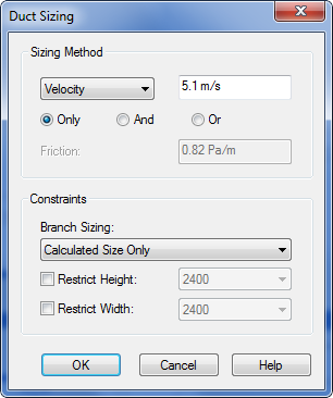
Click OK. You will see the ducts size is now changed.
To Sum Up
In this tutorial, you learned how to create route automatically, using suggested solutions by Revit.
You also changed the duct height and size automatically.
We will cover more in the next tutorial.


i want this project for training