In this Article...
AutoCAD default linetypes are usually enough for everyday purposes. But sometimes it’s just not enough sometimes we need to have our own. The problem is creating a custom linetype can be difficult to do. But if you have express tools installed, creating custom linetype can be very easy.
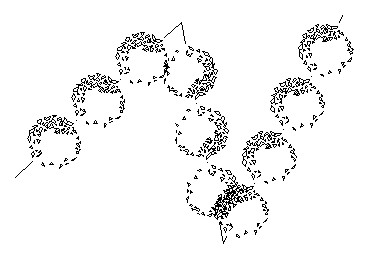
I like to use it, even for drawing complex objects. It is easier, faster, and consumes fewer hardware resources than using simple objects. Let’s see this object below.

I use lines to create these bushes. Only three lines. Imagine if you have to create it by using blocks then copy it several times. It could take some time. I’m going to discuss how we can make a custom linetype quickly. But remember, you have to have the express tools installed on your computer.

If you don’t have it, you need to install it first. See how you can add the Express Tools installation later here. It was for AutoCAD 2002 but will work the same for the later version.
Creating a linetype that contains simple objects
First, I’m going to create a simple one. I draw one line and one single line text as shown below.

I’m going to convert those objects to a custom line type.
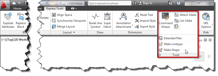
- Access from ribbon or AutoCAD Menu: Express>Tools>Make Linetype. Or if you are a command-line fan, you can type MKLTYPE.
- Type your line type file name, then click save. This filename is what you’ll see when you load the .lin file in the Windows dialog box.
- Type your line type name, then press [enter]. This line type name is what you’ll see in the name list.
- Type your line type description (optional), then press [enter]. This description should be able to give you a brief description of this line type.
- Specify the starting point and endpoint. In this example, I choose the left endpoint of the line as a start point. And somewhere slightly on the right of the text.
- Select objects. Select them both, then press [enter].
There you go. Change the line type properties, and try to draw lines, arc, or any other objects.
Linetype that contains more complex objects
If you have a complex object in the definition, the result can be unpredictable. Most of the time, the definition will be unusable.

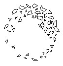
I will create a line type from this AutoCAD sample block. Insert to a drawing, and explode it. To create a line type from this complex geometry, we will have to create a shape file. Don’t worry; Express Tool also has an excellent tool to create it. From AutoCAD ribbon (or menu), choose Express>Tools>Make Shape. Or type MKSHAPE then [enter].
- Type the file name, then click save.
- Type the shape name, then [enter].
- Hit [enter] to accept default resolution value.
- Define the insertion point. The insertion point is as you define insert point in block creation.
- Select the shrub, then [enter]. The shape is created.
Now to avoid confusion, delete the shrub. Type SHAPE to insert the shape we just created. Type the shape name then [enter]. Press [enter] twice to accept the default value for scale and rotation. The same as you insert a block. Now, create a line type from the shape. Follow the steps in creating a simple linetype. Don’t you think this is cool? ;)
The line type scale doesn’t appear correctly?
If you have a problem controlling the linetype scale, you might want to see that you can control the linetype scale in 3 easy steps! You might need to have several attempts to work comfortably with it.
Video Guide
You can see how to create a custom linetype in the video below.


I made an additional dropdown menu for ACAD, which contains a large number of blocks needed for the development of power 0.4kV installations. All of them contain a leaf that, in the course of work and at the very end of the project, provide very useful reports.
1. Specification of equipment and materials
2. One-pole seed of each Distribution cabinet on the project
3. The balance of loading of each distribution cabinet on the project
4. The ability to easily select any block element in GRIP mode.
5. In this way, in addition to a visual display where blocks are selected by a certain criterion, there is also the possibility of correcting values in the ACAD propertis with one stroke.
https://www.youtube.com/channel/UCUhnyNLbbDKe2GNoCPQUrcg
having a problem of my linetyp not displaying on my layout page, any help?
I am creating a by six slash (three tilted to the left, three tilted to the right) composed of lines, use the command MKLTYPE , then it just become a straight line ,Looking forward to your reply.