In this Article...
AutoCAD default linetypes are usually enough for everyday purposes. But sometimes it’s just not enough sometimes we need to have our own. The problem is creating a custom linetype can be difficult to do. But if you have express tools installed, creating custom linetype can be very easy.
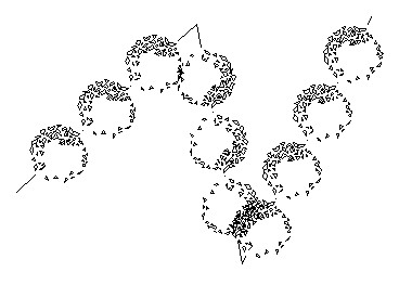
I like to use it, even for drawing complex objects. It is easier, faster, and consumes fewer hardware resources than using simple objects. Let’s see this object below.

I use lines to create these bushes. Only three lines. Imagine if you have to create it by using blocks then copy it several times. It could take some time. I’m going to discuss how we can make a custom linetype quickly. But remember, you have to have the express tools installed on your computer.

If you don’t have it, you need to install it first. See how you can add the Express Tools installation later here. It was for AutoCAD 2002 but will work the same for the later version.
Creating a linetype that contains simple objects
First, I’m going to create a simple one. I draw one line and one single line text as shown below.

I’m going to convert those objects to a custom line type.
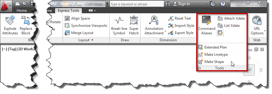
- Access from ribbon or AutoCAD Menu: Express>Tools>Make Linetype. Or if you are a command-line fan, you can type MKLTYPE.
- Type your line type file name, then click save. This filename is what you’ll see when you load the .lin file in the Windows dialog box.
- Type your line type name, then press [enter]. This line type name is what you’ll see in the name list.
- Type your line type description (optional), then press [enter]. This description should be able to give you a brief description of this line type.
- Specify the starting point and endpoint. In this example, I choose the left endpoint of the line as a start point. And somewhere slightly on the right of the text.
- Select objects. Select them both, then press [enter].
There you go. Change the line type properties, and try to draw lines, arc, or any other objects.
Linetype that contains more complex objects
If you have a complex object in the definition, the result can be unpredictable. Most of the time, the definition will be unusable.

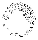
I will create a line type from this AutoCAD sample block. Insert to a drawing, and explode it. To create a line type from this complex geometry, we will have to create a shape file. Don’t worry; Express Tool also has an excellent tool to create it. From AutoCAD ribbon (or menu), choose Express>Tools>Make Shape. Or type MKSHAPE then [enter].
- Type the file name, then click save.
- Type the shape name, then [enter].
- Hit [enter] to accept default resolution value.
- Define the insertion point. The insertion point is as you define insert point in block creation.
- Select the shrub, then [enter]. The shape is created.
Now to avoid confusion, delete the shrub. Type SHAPE to insert the shape we just created. Type the shape name then [enter]. Press [enter] twice to accept the default value for scale and rotation. The same as you insert a block. Now, create a line type from the shape. Follow the steps in creating a simple linetype. Don’t you think this is cool? ;)
The line type scale doesn’t appear correctly?
If you have a problem controlling the linetype scale, you might want to see that you can control the linetype scale in 3 easy steps! You might need to have several attempts to work comfortably with it.
Video Guide
You can see how to create a custom linetype in the video below.


I created a a shada with a block of an arrow(perfect), the I created linetype with that shade… the only problem is that the arrow is very very little… i follow the tutorial to scale the line, but I can’t resolve this problem… can you help me please?
You are my hero!! thanks so much!! Just saved me a ton of extra work….
I’m trying to make a linetype with a shape in it. I created the shaped and have it saved on my hard drive. Now I want to incorporate this linetype into our company standards but when I do, the others can’t get the shape file. Where should I have saved the shape file so that everyone on the network can get this line type?
thanks
Hi Barbara,
You need to define the file location in AutoCAD support folder. Go to AutoCAD options, Files tab. Add the location in “support file search path”.
i have created a line type and line shape.but when i open that same drawing in any other PC that line shape and line type are not coming.It's coming in dot dot line can u give me a solution for this.
When you created the line type, a few files must of been created. .shx, .lin, .shp . These will need to be inserted into the support file path of the the other PC’s.
Thank you for the additional detail Symon.
I've tried to make a simple linetype with a solid line followed by a single line text. The linetype works except the text overlaps itself. I tried to choose an end point far to the right of the text which works but is hard to dial in the right spacing. Also, the text is not centered vertically on the line. I've tried different settings for "justify" text i.e. ML (middle left) with no change. Any tips?
i have try to make a line shap but i cant able to get that same shape which i have make only simple line is coming when i use that line type which i have make.even i have make that shape in polyline but i cant able to see that same shape which i have make.
This is great. You may not know, but I figured I'd take a shot. I'm using SprinkCAD in conjuction with AutoCAD and there is an option to "tidy pipe" which basically, i don't know what, puts a thicker linetype over anything that is drawn as pipe so that it is bolder and easier to see in the building layout…anyway I've created a line type with text as you've instructed. However when I finish my drawing and use the "tidy pipe" option, the thick line goes right over/through the text. It does not break at the text (or make bold text). I've tried changing the linetype in the properties manager for the tidypipe layer but it doesn't change anything. Any ideas?
hi zubair khan pls send me the answer
terimah kasih Pak Edwin Prakoso. byk ilmu saya pelajari daripada kamu.
Sorry, didn't work for me. I was trying to create a dashed line interspersed with diamond shapes. No matter what I do I just get dashes waaaaay apart interspersed with dots. This is
not a scale problem no matter how far you zoom in the dots are really there. Object is just a square at 45 degrees.