In this Article...
Do you think setting up lights for AutoCAD rendering is difficult? Or do you think trial and error for setting up AutoCAD lights take too much time? Not really. In this rendering tutorial, you will learn to setup the sun light easily and a little trick to speed up the rendering test. This is the second part of our rendering tutorial. We have defined our camera view in previous tutorial. Next, we are going to define the AutoCAD lighting. We will discuss sun light (or natural lighting) and artificial lighting separately. Sun light comes first. Lighting is one of the most important thing in rendering.
If you already downloaded the DWG file from the previous tutorial, I apologize. I forgot to add floor to the model, you can download this one to continue with this tutorial. And of course, you can use your own model.
Turning Off Materials
Why not we define the objects’ material first? Setting up rendering light can take a lot of time. You need to do several rendering tests until you get what you want. Having your materials defined already, will make the rendering slower. Especially when you have many reflective and transparent materials. With no materials defined, the rendering will be faster to get the proper lighting. After we satisfied with the lighting, then we define the materials.
First, we need to turn the material off. Go to render tab, materials panel. Check if the materials/textures off. Turn it off if it’s still on.

This is a pretty simple model. If your model have several windows or opening, you can try to set the light to come through from your preferred opening/window. Our objective is to get the solar light come through from the window, and in this model we only have one. So let’s turn off the window’s glass layer. In this file, the layer would be 3D-GLAZ-GLAS.
The next layers you are going to turn off is totally up to you. In very complex model, it would be wise if we turn off objects that is not too important in setting up lights. If you have powerful machine and working on a relatively small model, you may not feel the difference. But when you have a bit old machine and the model has many geometries, then this can help. This model is quite simple, but let us hide the furniture to set up our lighting fixtures. Leave the wall, ceiling, and floor layers on.
Geographic Location
To define the solar light properly, we need to set the geographic location. Click set location in Sun & Location tab.

AutoCAD will give you options how you want to define the location. For this tutorial, choose enter location values. We will have another dialog box opened. You can define the location by typing the latitude and longitude. Or simpler way to do it is by using use map.
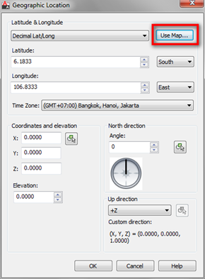
Pick your location and click OK until all dialog are closed. I use Jakarta as my location. Your result will look different if you choose other location. But it doesn’t matter.
Sky and Sun Properties
Now let us turn on the sky. If we don’t turn it on, the sky will be black. Not so nice for daylight rendering, right?

Next, let us set the sun. click the sun status icon.

When you do it for the first time, AutoCAD will give you some options. Choose to turn off default lighting. Default lighting is ugly. We are going to use natural light from the sun. After you turn off the default lighting, you could see the date and time slider active.

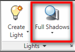
Turn on shadows. Change the setting from no shadows to full shadows.
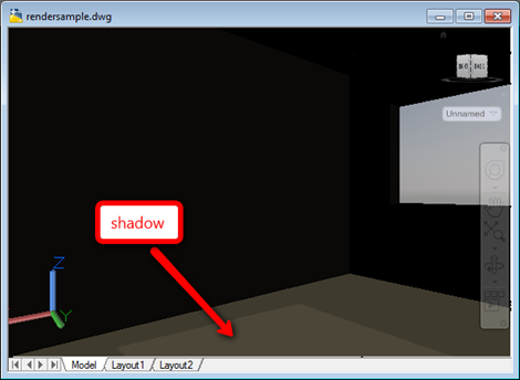
Now try to change the date and time until you can see the sun light come through the window. Do it until you feel the light angle is good. In photography, morning and afternoon sun light is considered as the perfect time. It gives a great lighting depth and covers wider area than when the sun right above your head.
Rendering test
We are going to test our light settings, but this is not a final render yet. So you can use lower quality to render it. I suggest you to try on medium quality. Draft and low quality give very rough lighting effect. Medium quality is more relevant. Click the small arrow on the lower right of render panel to open advanced render settings.

In the advanced render settings, change the render quality to medium. And find indirect illumination category in that palette. Click the light bulb next to global illumination to turn it on.
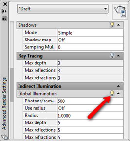
Without indirect light, we will not see the effect of the bouncing lights. Turning it on will make the rendering longer. If you are experienced, you may be able to predict the final result without turning it on. But let us try with the indirect light on. Click render and wait a few minutes to see the result.
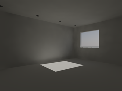
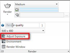
I think this is nice. Now let us adjust the exposure. This is totally up to you. I feel the render result is not bright enough, and not enough contrast. So I will adjust them. Click adjust exposure to open the dialog.
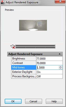
AutoCAD will open a dialog. There are several settings that you can change to make the rendering result nicer. You can click the up and down arrow or simply type new value. The preview window will update as soon as you change the values. Do it until you feel it’s good enough.
Now let us test the rendering again. This is what I get. Better, right?
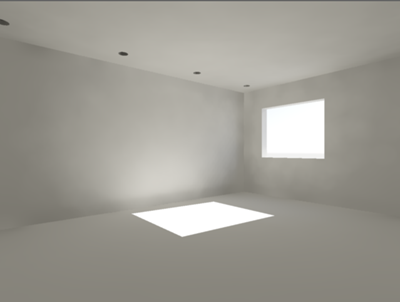
Remember, in the real rendering setup, you may need to do several trial before you get satisfied result. And finally, after we feel it’s nice enough, test it with your objects on.
Not bad, isn’t it?
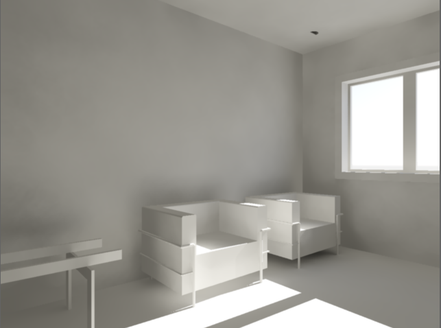
If you are using your model, and have different result with mine, I would like to see how it looks. And I believe the others would like to compare with theirs. So put in on you blog, Flickr, Photobucket, CAD Notes facebook page, or anywhere people can see it. Share the link to your rendering result using the comment form below.
Aren’t you feel excited how the result would looks like? Keep following this tutorial! We will do it together!


Yang bahasa indonesia ada gak mas.
HI,
But I can’t find the global illumination and indirect illumination in Acad2017
Hlo sir u r doing such a great job.