In this Article...
Preface
This tip shows how to control display behavior if linked files overlap some objects in Revit. In some cases you might have met problems with correct display of linked objects located above other objects. You need to control display behavior of overlapping objects. If you know AutoCAD, you may remember command like DRAWORDER to solve the problem. How shall we do it in Revit. The answer is easy, just read this tip, please.
Example: You linked DWG with floor plan and created walls overlapping positions of doors and windows.
Tutorial:
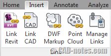
1. Link CAD file (eg. DWG file) via tab Insert – Link CAD
2. Create walls (tab Home – Wall) using some methods (individual sketch or picking lines).
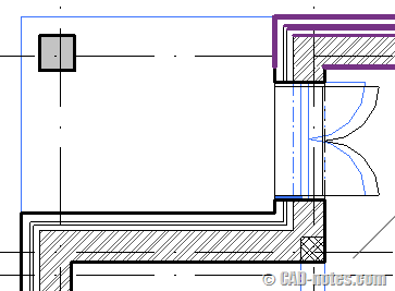
Situation: At this moment walls are overlapping sketch in imported symbol of CAD file and you don’t see positions of opening, windows, doors for insert objects in Revit model.
Workaround of control draworder in Revit:
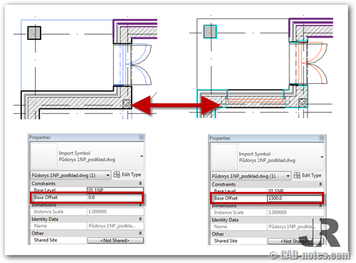
3. Select imported symbol and display palette Properties.
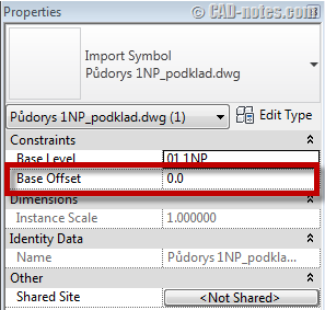
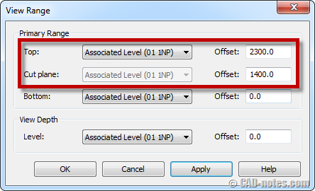
4. Set Base Offset to value among Cut Plane – Top in View Range of Floor Plan.
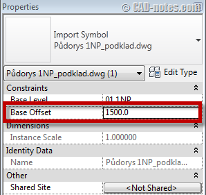
5. Now, you can see the difference:
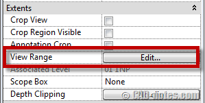
Notice: Remember the value for Base Offset imported symbol must be among values for Cut Plane and Top in View Range for Floor Plan. To setup View Range parameter go to Properties palette if nothing in view is selected and click Edit.
In dialog View Range you can set the range of view.
Hope the tip helps you.


some times base offset is not viewing the properties pallet for new imported cad file can any one help me out
You can use this tip for Revit 2011 and older. In Revit 2012 is property for control display imported symbol (foreground, background).
foreground/background is available only if you select "current view only"
I am having the same issue but its a linked revit model.. so i cant change the elevation of the revit link or else it would mess up the whole project… what should i do?
You can also just turn on wireframe in the view to reveal the CAD file.