• Home
  • Training Books
  • Subscribe to Our Email Newsletter
  • About
    • Contributors
    • Feedback
    • Contact
    • Privacy policy
    • Cookie Policy

CADnotes

CAD Tutorials and Best Practices for professionals and students

  • Featured
  • AutoCAD
    • AutoLISP
  • Revit
    • Revit Architecture Basic
    • Revit MEP Basic Tutorial
  • Inventor
  • MicroStation
    • MicroStation Basic Tutorial
You are here: Home / Revit / Working with Revit temporary dimension

Working with Revit temporary dimension

July 15, 2014 by Edwin Prakoso 3 Comments

In this Article...

  • Changing temporary dimension settings
    • What are the differences between options?

When you place an object in Revit model, you will see temporary dimensions. It will guide you to place the object accurately. The problem is the dimension will measure object placement from nearest face. Not from centerline.
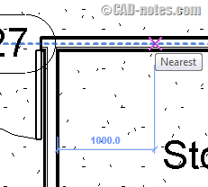
create_temporary_dimension

Revit temporary dimension also measure from face when you modify objects. In this example, I select a wall to move it. Many of you already know that we can move the witness line if we want to adjust the temporary dimension.

You can drag the control point to new location. Or simply click it to cycle between faces or centerline.

But it means more clicks to accomplish a simple task.
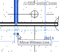
move_witness_line

Changing temporary dimension settings

In my country, we almost always refer to centerline. If you also mainly use centerline as reference, then you should change the settings. You can find temporary dimension in Manage tab> Settings panel> Additional Settings> Temporary Dimensions.

temporary_dimensions_settings

In temporary dimension properties, you can change where it should measure when you place or modify objects.
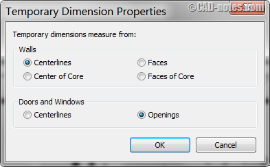
temporary_dimension_properties

What are the differences between options?

In walls measurement, there are centerlines and center of core. Faces and faces of core. What is the difference?

Centerlines lies in the center of the entire wall layers. And faces are the exterior/interior of entire wall layers.

What about core? What is that?

If you remember how to define wall layers, you can see the core there. Below, you see the masonry concrete block is the only layer in core. Any layer between core boundaries is the core.
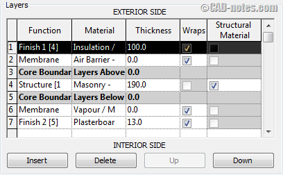
wall_layers

So the center core or core faces will refer to those layers within core boundary. If you see the preview, the core is between between the green lines.
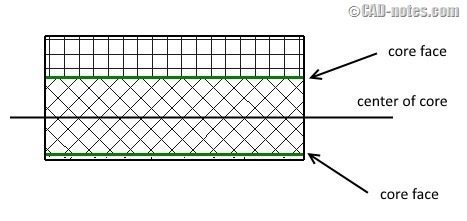
wall core

You can change the temporary dimension settings to your preference. So you can work fast and accurate. If you need to adjust the temporary dimensions when you work, simply move the witness line. Either by dragging the control point or clicking it.

About Edwin Prakoso

I work as a Sr. Consultant in PT Cipta Satria Informatika. I've been using AutoCAD since R14 and Revit since Revit Building 9. I occasionally write for AUGIWorld magazine and I am also active in Autodesk discussion forum. I'm a member of Autodesk Expert Elite, an appreciation for individuals who give contributions to the Autodesk community.
Connect with me on twitter or LinkedIn.

Filed Under: Revit Tagged With: temporary dimension

0 0 votes
Article Rating
Subscribe
Login
Notify of
guest

guest

This site uses Akismet to reduce spam. Learn how your comment data is processed.

3 Comments
Inline Feedbacks
View all comments
Vanessa Josephson
Vanessa Josephson
10 years ago

I also change the settings in Manage > Settings > Additional Settings > Temporary Dimensions. I always change it to “Face of Core”, but my temp dimensions still go to the center! This is very irritating especially on exterior wall dimensioning. I want to see at a quick glance my overall dimension, not the overall center-to-center dimension. Why does my setting not do what I told it to?? THANKS!!

0
Reply
Steve Bumbalough
Steve Bumbalough
10 years ago

Edwin, very nice tidbit. Have you found such a setting that allows standard linear finish dimensions to measure from faces of core?

0
Reply
Edwin Prakoso
Edwin Prakoso
Author
Reply to  Steve Bumbalough
10 years ago

Hi Steve,

You can find the options in option bar. But only if you use aligned dimension, not linear dimension.

0
Reply
wpdiscuz   wpDiscuz

Featured

Work Better with AutoCAD | Challenge 3: Reusable content

In this week Work Better with AutoCAD challenge, you will create reusable content: AutoCAD Block. You have chance to win an e-book just to participate in this challenge. Or win a grand prize after all challenges are given!

Recent Articles

  • Autodesk Construction Cloud Activity Log
  • Exporting AutoCAD Plant 3D Model to Navisworks
  • Autodesk Data Connector for Power BI is Now Available

Advertisement

New on CADnotes

  • Autodesk Construction Cloud Activity Log
  • Exporting AutoCAD Plant 3D Model to Navisworks
  • Autodesk Data Connector for Power BI is Now Available
  • Autodesk Forma Design Contest
  • Revit 2025: Toposolid Enhancements

Meet the Authors

avatar for
avatar for
avatar for
avatar for
avatar for
avatar for

Get Connected

CADnotes on FacebookCADnotes on InstagramCADnotes on TwitterCADnotes on YouTube

© 2009 – 2025 CADnotes · Feedback · Privacy Policy · Become an affiliate

wpDiscuz