In this Article...
We created a pipe drain route. Now we are going to modify it. We will add slope to this pipe. We will also change the pipe size in several sections.
Open your Revit MEP tutorial file. Open 3D plumbing view.
Isolate the pipe in view
Zoom in until you can see the drain pipe easily. Make sure you have Modify command active. Press Esc a couple of times if necessary.
Move your mouse cursor over a drain pipe. Don’t click the pipe yet. Press TAB key twice on your keyboard until you see the pipes are selected.
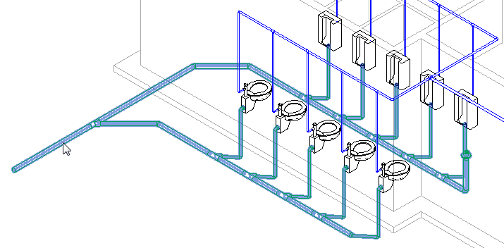
You should see this in status bar:
![]()
Click your mouse to select the pipes.
Pressing TAB will cycle between objects selection. You can press TAB to cycle between overlapping objects or to select connected objects.
With the pipes are selected, press HI to isolate the elements. Now we only see the pipes in our view.
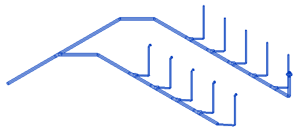
Changing the pipe size
Change the pipe size from water closet
Zoom into the pipe near water closet. Hold the CTRL key and click pipes and fittings highlighted below.
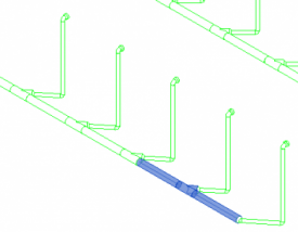
Holding CTRL key allows you to add more objects to the selection set. You will see + sign near your mouse cursor when you press CTRL key.
In the options bar, change the diameter to 80 mm.
![]()
Notice that Revit will Automatically add reducer when necessary.
Change the pipe size from urinal
Before you start changing the pipe size from the urinals, you need to change the floor drain size first. Select the floor drain.
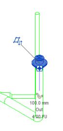
From Type Selector, change the floor drain type. Select 125 mm Strainer – 50 mm.

With the same method we did before, change the pipe size to 50 mm and 65 mm. See image below as a reference. Remember that you also need to select the fittings to change the pipe size.
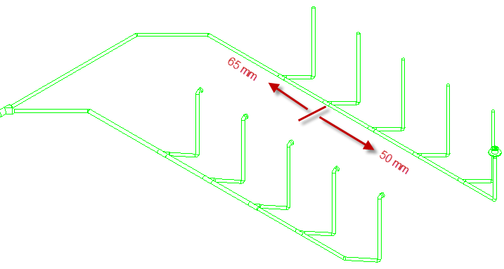
Revit MEP has a tool to calculate the pipe/duct sizes automatically. We will cover about this later.
Changing the Pipe Slope
Next, we will add slope to the drain pipe. Select all the pipes. You can place the mouse cursor above a pipe then press TAB like we did before. Or you can windows selection all the pipes.
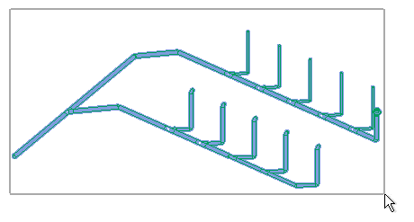
Click the filter tool on your Contextual Ribbon TAB> Selection Panel.

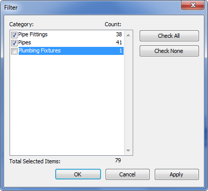
In the filter dialog box, uncheck Plumbing Fixtures. Leave Pipe Fittings and Pipes checked. The plumbing fixtures will be excluded from the selection set. Click OK.
Click Slope from the Contextual Ribbon Tab> Edit panel.

In the next Contextual Ribbon Tab, change the Slope Value to 1%. Click Finish.

You might see this warning message after you finish this slope tool.

Revit will highlight the pipe below in 3D view.
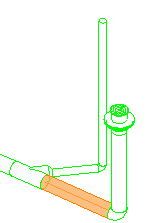
Revit can’t apply the slope value to this pipe, so we will need to fix this. Revit applied the slope, but it’s not 1%.
Select the pipe, elbow, and vertical pipe to the floor drain. Press delete on your keyboard to delete them.
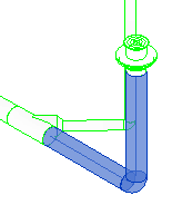
To reconnect the pipe, go to view 1- Plumbing floor plan.

Select the Y fitting. Right click above the connector and select Draw Pipe from contextual menu.
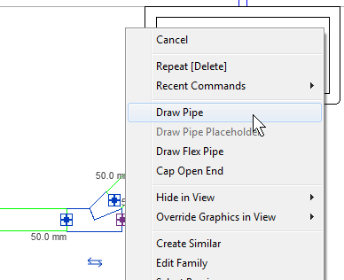
We want this new pipe to have 1% slope, so in Sloped Piping, activate Slope Up and change the Slope Value to 1%.

You can define Pipe Slope when you first start placing the pipe by setting this option.
Now connect the fitting to the floor drain.
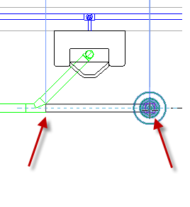
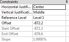
Examine the completed model in 3D view. Select the pipe you added and check it’s properties on Properties Palette.
Notice that now the Slope is 1%.
Having a Problem Following the Tutorial?
Watch this video for your reference.
We will create HVAC route in the next tutorial. We will use more advanced features, I believe you will have fun!


These tutorials make me grow in Autocad, I am basically working on civil engineering and topography dwg
My problem is on scale annotations say 1:50000 why objects don’t change with scale except text only