We have done with modeling our building for now. After we placed Revit components, now we can produce descent drawings. Well, we haven’t learn about curtain wall and site/topography which I plan to write later. But let’s have fun for a while. We are going to discuss about the other modeling technique in Revit later, not in this tutorial series.
Now we are going to annotate our Revit model.
Annotation is a very important component in your design. Doesn’t matter if you model it in 3D, you will still need to plot it to 2D drawing. And you need to provide information with annotations. There are many types of annotations in Revit, like dimensions, tags, building elevation symbols, sections symbols, etc. Some annotations added automatically when you created a view. Now let’s discuss about dimensions.
Arranging Elevation View Symbols
First, let’s arrange our elevation views symbols. Open your 1st floor plan. Select west and east view in your drawing. Delete it. We won’t need it since our model only have two faces: from front (south) and back (north).
Now select south elevation. We are going to move it closer to our model. If we don’t do this, we will have a lot of empty space when placing this model to sheets. Elevation view symbol consists 2 (or more) elements. To make sure we select all of them, drag your window selection from right to left. This will select all objects that touch our window selection.
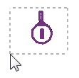
Activate move from your ribbon
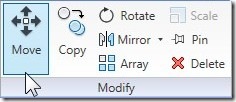
Move it up closer to our model. Do the same with north elevation view.
Why using move? Why not just drag them? Sure you can move objects by dragging it. But using move will restrict the movement to vertical (or horizontal). Not freely as using drag.
Adding Dimensions
Adding dimension is very easy. Open your annotation tab. Activate ‘aligned’ dimension.

By default, the options to place dimension are by wall centerline and individual reference.
![]()
Let’s just use it. Move your pointer to a wall, you should see the centerline is highlighted. Select walls as shown below, consecutively from 1 to 4.
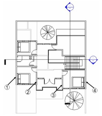
After selecting those 4 walls, move your pointer down. You should see your dimension now. Click where you want to place it. Add one more dimension to show the distance from wall 1 to 4.
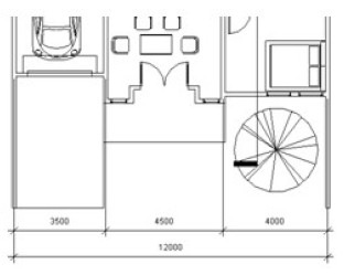
Peace of cake!
Now with linear dimension still active, change in your option bar pick:Entire Walls. Click option button on it’s right.
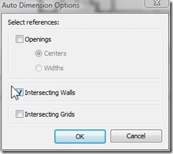
Activate intersecting walls, then click OK.
Select wall no 1 (on previous dimensioning). See what happen. We don’t need to select dimension individually anymore! Now you can finish your entire dimension right?
Turning Underlay Off
Open your 2nd floor plan. You might see your first floor plan here in grayscale (opaque). It’s on by default, make us easier to use level underneath it as reference. But we don’t need it anymore.
Open you view tab in ribbon, activate View Properties. Or you can press VP consecutively. Find underlay parameter, and change the value to none.

Now, add all dimension you need. Very easy, right?
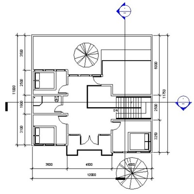
Just in case you need other type of dimension, you can see it in dimension group.

*You can purchase this tutorial compilation in an e-book. Find out the books in our E-Store .


COMO PUEDO HACER PARA NO PERDER COTAS EN EL ARCHIVO GENERAL DONDE TENGO LINKEADO MUCHOS ARCHIVOS.
ESTOY TRABAJANDO EN UNA MANZANA CON MUCHOS EDIFICIOS (ARCHIVO GENERAL DONDE ESTAN LINKEADOS LOS ARCHIVOS DE ARQUITECTURA DE TODOS LOS EDIFICIOS),
POR CADA EDIFICIO TENGO UN ARCHIVO DE ARQUITECTURA Y OTRO DE ESTRUCTURA.
EN EL DE ARQ. TENGO LINKEADO EL ARCHIVO DE ESTRUCTURA. ATACHADO. PUEDO ACOTAR PERFECTAMENTE, ACOTANDO EN ARQUITECTURA LOS ELEMENTOS DE ESTRUCTURA.
PERO AL LINKEAR EN EL ARCHIVO GENERAL SE PIERDEN LAS COTAS QUE ACOTAN ELEMENTOS DE ESTRUCTURA.
AYUDA PLIS!!
Very helpful. Thank you.