In this Article...
If you enjoy tinkering with AutoCAD, you may have noticed how every command is triggered by a complicated looking bit of text. If you don’t know what I’m referring to – type ‘cui’ at the command line and select one of the commands in the bottom left window. You should see something like this:
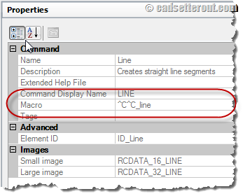
This command string:
‘^C^C_line’
Is known as a command Macro, and you can create your own command Macro’s to help speed up your workflow.
In this post I want to share some commands Macro’s that I use to help me speed things up when I’m working with AutoCAD’s paper space viewports, and I’ll show you how to set these up on a tool palette for easy access.
Setting up.
Before we start work, I want you to open up your company standard AutoCAD template DWG file. Navigate to paper space, make your company standard viewport layer active and create a viewport. I’ve used a layer called ‘VPORTS’ for this exercise, but you should use the appropriate standard layer.
Tip: If you don’t have a company standard template read Edwin’s excellent post on templates here.
Setting up a tool palette.
In this post I am advising you to host your new tools on a tool palette, simply because tool palettes are easy to set up, maintain and migrate. You could apply these techniques in the CUI instead and build your custom commands into a tool bar or ribbon tab… but that’s for another time.
To open the tool palettes go to:
View Ribbon tab > Palettes panel > Tool Palettes
Or type ‘toolpalettes’ at the command line and hit Enter.
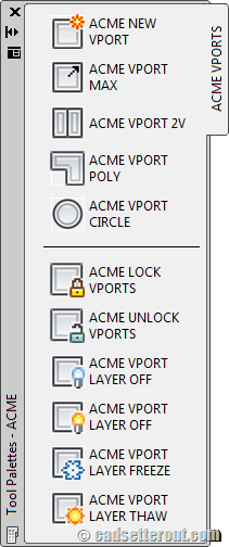
Now you have your tool palettes open, right click over any palette and choose ‘New Palette’. You can name your new palette anything you like; I’ve called mine ‘ACME VPORTS’.
Note: Tool palettes are not saved until the drawing is closed.
Creating a new tool
The next part is the fun bit. Click on the viewport you created earlier and drag and drop it onto the tool palette. You have now created your first tool – that was easy!
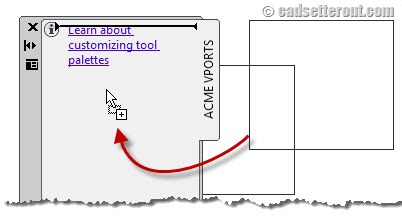
Note: Left Click on the viewport once to select it. Now with the viewport selected, left click again and hold the left hand mouse button down. You can now drag the viewport onto the palette to create the tool.
To test your tool, click on it. You should be prompted to draw a viewport. Once you’ve created a viewport, click on it once to select it. Notice which layer it’s on? That’s right; your new tool has created a viewport, on your company standard layer and it didn’t even change the current layer while it did it.
Note: This tool will also create the layer it needs if the layer does not already exist in the current drawing file.
I hope that you are already impressed – but we can do more.
How does it work?
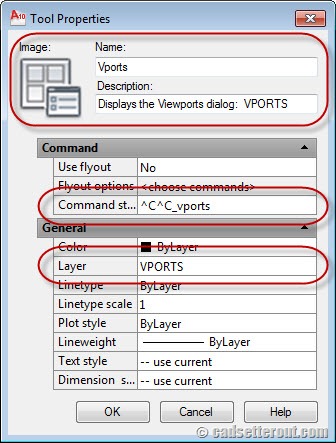
To see what the tool is doing, right click over it and chose ‘Properties…’. I hope you notice the ‘Command string’ box, about half way down. The command string that this tool is running looks like this:
^C^C_vports
The ^C part of the macro is equivalent to pressing the ‘Esc’ key – it cancels the current command. This command uses ^C^C because some AutoCAD commands need two ‘escapes’ to completely cancel out of the currently command. It is good practice to start all your command Macro’s this way.
Note: Can you think of an AutoCAD command that would need THREE ‘escapes’ to fully cancel out of it? Answers in the comments please…
The underscore before the command is used to ‘Internationalize’ the command. If you are not working with the English language version of AutoCAD the command names will have been translated. The underscore tells AutoCAD to use the default English version of the command.
The ‘vports’ part of the string is exactly the same as typing ‘vports’ at the command line.
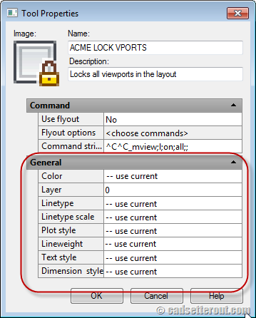
I also want you to notice the boxes under the ‘General heading’. You can see that this tool will create a viewport on the ‘VPORTS’ layer, and you can also override some of the other properties here.
Applying a little finesse.
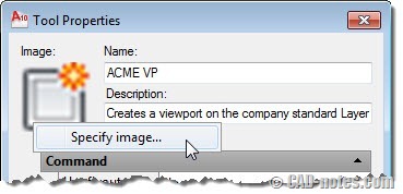
There are a number of ways that you can personalize your new tool. You can change the name to something that makes more sense to you. You can change the description (the description value becomes a handy little tool tip when you hover over the tool on the palette). You can also change the picture by right clicking over the picture and choosing ‘specify image’.
Back to the Macro.
In this case the command string that has been created uses the ‘vports’ command by default. However, the vports command also has a purpose in Model space. Let’s change the tool to use the ‘mview’ command instead, which only works in paper space.
All you need to do is change:
^C^C_vports
To
^C^C_mview
More viewport creation tools.
To create more tools, just right click over the tool and chose ‘copy’ and then hover anywhere over the blank palette and choose ‘paste’.
Here is another example of an alternative command macro you could use:
^C^C_mview;f;
The semi-colon ‘;’ in this command strings is just like pressing ‘enter’ on your keyboard. So the macro could be read as:
Hit ‘esc’ twice, type ‘mview’ at the command line, hit ‘enter’, type ‘f’ at the command line and then hit ‘enter’ again.
Try it out. What do you get?
That’s right – a viewport, taking up all the available room on the drawing sheet. Writing this into a command Macro allows us to do all that with a single click!
How about this one:
^C^C_mview;2;v;
This command string launches the Mview command with the ‘Two viewports, vertically aligned’ options current. Just two clicks to create two viewports, on the right layer.
Here’s one more:
^C^C_mview;p
This command string uses the Mview command with the ‘Polygonal’ option to create an irregular shaped viewport.
The final one in this section gets a bit more complicated:
^C^C_circle;\\_mview;o;l
This command string creates a circular viewport. It does this by running the circle command, and then immediately afterward, running the Mview command using the option to create a viewport from the last object created, in this case our circle.
The two back slashes ‘\\’ are interpreted as pauses. In this case the user must pick the centre point and radius of the circle. This is two clicks – therefore two back slashes.
Note: It is not easy to include error checking in a command macro. In this case the macro expects two clicks, if the user decides to choose a method of creating a circle other than ‘Centre radius’ the command will fail. If you need to include error checking in your Macro’s you may need to use Lisp.
Locking and unlocking viewports globally.
For the next example, I want you to copy your tool as you did before; but this time, open the tools’ properties and set all the values in the ‘General’ options to ‘use current’ except the layer control, which you should change to ‘0’. In this case, our macro won’t be creating any geometry, so we don’t want those properties set.
The next example will help us speed up locking and unlocking viewports:
^C^C_mview;l;on;all;;
Run the command and then hit F2 to bring up the AutoCAD text window. Have a look to see what commands the Macro is executing…
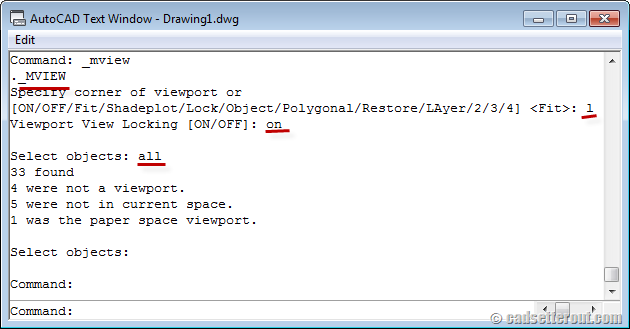
That’s right; this command string locks all the viewports in the current layout – very handy to run before you close down your drawing for the day.
The reciprocal is this, which unlocks all the viewports in the current layout:
^C^C_mview;l;off;all;;
Turning the viewports layer on and off
To turn the ‘VPORTS’ layer on and off, we need to use the ‘layer’ command. Copy and paste the tool as before, and add this command string to turn the ‘VPORTS’ layer on:
^C^C_-la;on;VPORTS;;
And this command to turn the ‘VPORTS’ layer off.
^C^C_-la;off;VPORTS;;
I hope by now that you can work out what these macros are doing. If you aren’t sure, click the button to run the macro, and then hit F2 to bring up the command window and see what’s happened.
Note: Replace ‘VPORTS’ with your layer name. If you layer name contains a space, make sure that you put the layer name in quotes e.g. “VPORTS 1”. The layer name is not case sensitive.
Freezing and thawing the viewports layer
If you would prefer to freeze or thaw the VPORTS layer, you can use these two macros instead.
To freeze the ‘VPORTS’ layer:
^C^C_-la;f;VPORTS;;
To thaw the ‘VPORTS’ layer:
^C^C_-la;t;VPORTS;;
Round up and further reading
I hope that you enjoyed this post and that you found it useful. If you have any questions, please leave a comment below.
If you’d like to know more about Tool palettes, Edwin has a great tutorial here:
https://www.cad-notes.com/2009/09/creating-your-own-autocad-palette/
If you’d like to know more about command macros check out the developer help files. You can find the help files online here http://cadso.co/t17wRy.


Its realy awesome…I have been working on autocad from last 10 years. Still finding every time new things..I would like learn more things..
Thank you.
that is awesome thank you on this information’s keep going man
No Problem Hossam :)
For more like this, check out Sam Lucido’s class at Autodesk University (Free Autodesk Account required):
http://au.autodesk.com/au-online/classes-on-demand/class-catalog/2014/autocad/ac4873#chapter=0
Paul
Useful piece . With reference to which , if your company is looking for a service to merge some PDF files , my employees stumbled across article here http://goo.gl/yr3wme.
Hello there,
Amazing article! I am now having fun speeding up everything in Autocad.
But there’s a small detail I can’t fix : how did you get the icons for the tools? I found “acadbtn.xmx” which is said to have icons for Autocad, but I can’t extract them from gere, and I’m a bit lazy to manually extract them with a Print Screen-ish technique.
Thanks!
Hi Thibault,
In AutoCAD type ‘CUI’ to open the Customisable User Interface editor. Select a command in the bottom left hand window and the commands details will appear in the top right window.
Under the icon for the command you will see two buttons ‘Edit’ or ‘Export’.
I hope that this helps!
Does anyone know Thibault can export the whole lot all at once?
Paul
Hi, thanks for the answer.
Actually I knew commands can be customized here, but the palette tools aren’t appearing there! I would like to have palette tools (which can be further set up like changing layer, line thickness etc.) but with an icon to help recognize them (and to make them look prettier!). I found a way to get through this by creating a command, putting it in the palette and then setting it up but it is a bit messy. When I right click on the palette tools, and on the image, Autocad doesn’t asks for the autocad icons list but only for a home made icon.
Thanks for your help!
Ahh! OK, try this. Right click over your tool palette and choose ‘customise command’. This will open a version of the CUI editor.
Choose the command that you want to make a tool of and drag it onto the tool palette. This will build a tool that has the standard AutoCAD icon.
Is this more helpful?
Forget it, I read the part where you say we can export icons too fast.
Problem solved!
Sorry I was trying to comment to: https://www.cad-notes.com/how-to-automate-autocad-with-command-macros/
I had gone there from this link. It’s under AutoCAD Macros section The Good –
Ah I see :)
Thank you for reporting this typo!
Love the site!
Spelling error – Macros can also contain DIESEL not DIESAL code.
Only brought it up in case someone searched for it in help.
Hi Tom,
I can’t find DIESAL word in this post. Can you guide me so I can fix it?
Thank you for notifying us!
Use ^C^C^C if you are silly enough to be clicking on a macro while halfway through another command. People like you should stick to ACAD LT.
In your note above about creating the new tool you state to select new item(viewport)you left click then left click again & hold mouse button down,it`s actually the right button you click & hold the second time to drag & drop.Took me a while there to figure.
Hi m4rtymcf1y.
Thanks for taking the time to leave a comment.
Both left click and drag, and right click and drag work for me.
-Paul-
3 escapes required when using a transparent command in a command that already needs 2 escapes!