
Let’s continue our AutoCAD dynamic block tutorial. We have created a basic dynamic block tutorial by adding one stretch action to our wall block. We will discuss further about parameter properties in this post.
Now let’s talk about what we want to achieve. We want one block that contain several column size. But column size is not supposed to be modified by freely stretching it. We have to limit the column minimum and maximum size. And we also have to set the increment value for this size, so the changes can be predictable.
If you’re not familiar with dynamic block, you should read this tutorial first. Basically we are doing the same thing, but there are some properties we are going to change. As we did when we create wall, we have to add some layers. Let’s add these layers:
- A-Column, color:green, lineweight: 0.20
- A-Column-Pattern, color:8, lineweight: 0.00
- A-Column-Structure, color:9, lineweight: 0.09
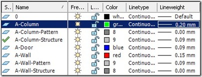
Let’s create our column. Set layer A-Column as current layer. Draw a rectangle with size 400x400mm. Change your current layer with A-Column Structure, then offset your rectangle by 20mm. Remember to set the offset object layer to current. So this operation will create a new object on current layer. Offset it to the inside of the existing rectangle.
Command:
OFFSET
Current settings: Erase source=No Layer=Source OFFSETGAPTYPE=0
Specify offset distance or [Through/Erase/Layer] <20.0000>: l
Enter layer option for offset objects [Current/Source] <Source>: C
Specify offset distance or [Through/Erase/Layer] <20.0000>:
Select object to offset or [Exit/Undo] <Exit>:
Specify point on side to offset or [Exit/Multiple/Undo] <Exit>:
Select object to offset or [Exit/Undo] <Exit>:
The last one, set your current layer to A-Column-Pattern. Fill the inner rectangle with concrete hatch.
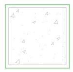
Create a block from these objects. Make sure the insertion point is the column center.
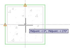
Give the block name ‘Rectangular Column’. After you finish defining the block, open block editor and edit it.
Similar to what we did in creating wall, we have to add parameters. This time we need to modify the column length and width, so we need to place 2 parameters.
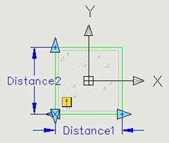
Select the Distance1 parameter, then open properties palette.
- Change the parameter name to ‘width’.
- Change the distance type to increment.
- Set the distance increment to 100
- Set the distance minimum to 150
- Set the distance maximum to 600
- Under Misc category, change the base location to Midpoint.
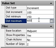
Do the same thing to Distance2.
I think you already know what to do next: add the stretch action. But this time you add it to the both sides. Refer to the dynamic block #1 tutorial.
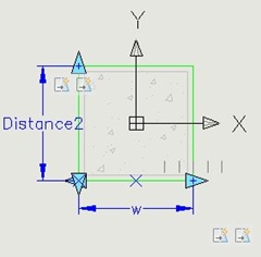
After you finish, close dynamic block editor. Try your block!
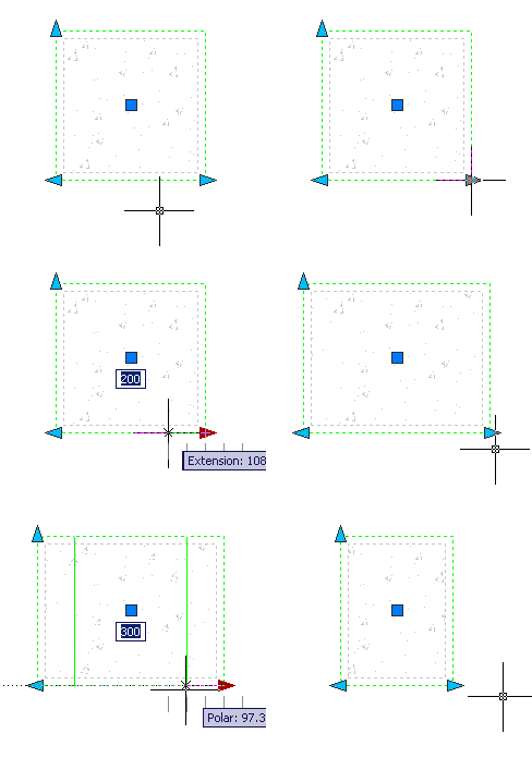
You should see some thick mark every 100mm between 150 and 600. Oops, my bad! You can’t create 150mm width column because we set the increment to 100! The minimum width you can achieve is 200. You have to change the increment to 50 to get it.
We also changed the base location to midpoint. So when we stretch it, it will be stretched both way. Not so difficult creating dynamic block, isn’t it?


Thanks again for an other great tutorial!
I saw a very small error. You mention 100 as increment, I think you ment 50, no?
Tss…
Before adding a comment, read it all.
Sorry. ;-)
Missing Instruction: Select the second Stretch Action once it is created, the one at the opposite end, and set the “Angle offset” property to 180. Otherwise the block will simply appear to move in the direction you are trying to stretch it … which is absolutely correct as both ends are stretching in the same direction. Without the above, this exercise will drive you mad for at least a day until you figure it out.
Have fun :)
yes u r right
sir I want to know about the annotation scale ? Could you please help me
Hai Edwin Prakoso,
saya kerja sbg drafter di Belanda.
saya mengerti cara kerja visibility dr dynamic block.
tapi apa kegunaan dan apa beda look up & block table dibandingkan visibility?
Sir Edwin,
I find it hard and need more practiced to do it.. Finally I got it.. The reason why i didnt get it quickly because of the parameter 2… I got confused..it can be done using only one parameter (width).. what is the use of parameter 2 if that is the result? thanks sir…
how can you use two mid point at once???
See object snap tracking in this tutorial: https://www.cad-notes.com/2010/02/autocad-precise-inpu…