 Let’s go further with our Revit tutorial. In the last tutorial, we learn about creating floor. Now we are going to create roofs. There are 3 ways to make this building component. By footprints, extrusion, and by face. In this tutorial, we will discuss about creating it by footprints.
In your Revit project, open your floor plan view: roof. We will create two roofs at this level. First, a slab surrounding our building as concrete gutter, and a sloped roof. (I hope I use the right term, not really familiar writing this in English).
Creating slab
Using footprint method is similar with creating floor. We will have to sketch it. You can access this tool from your ribbon, build group. Clicking this will bring you to sketch mode.
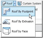
What we will do is exactly the same with what we were doing when creating floor. You can either using pick walls or by drawing lines. To create this slab, deactivate define slope.
![]()
Click properties button at your ribbon. Change your family type to Generic – 125 mm.

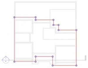
Draw your sketch as below. At this example, I create the left and right line by picking walls, and finish the rest by using line sketch with 500mm offset. You can change the offset value on option bar, then snap to your walls.
![]()
Don’t worry about the exact size. You can change the values as you feel appropriate. Remember: make sure it’s a closed polygon.
Now, change the offset value to 800, and create another polygon inside the first one.
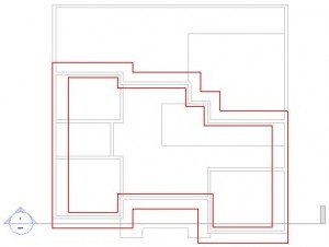
After you finish, click finish. When Revit ask your confirmation to attach your walls to this roof, select no. Review your model in 3D view if necessary.
Creating Sloped Roof
Next, we will add a sloped roof at this level. Open your roof’s level plan.
Activate roof by footprint tool. This time, make sure define slope option is active. Click properties, change ‘Base Offset from Level’ value to 200. This will create your roof 200 mm above the level.
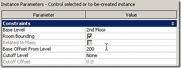
Now, use the line mode for drawing your sketch. Change offset value in the option bar to 200. Create your sketch by snapping to the slab you created before.
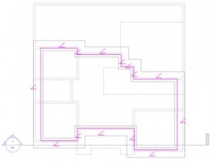
Click finish roof, and review your model in 3D view. Very easy, right? Let’s do some modifications. Open your roof plan view, then select your sloped roof. Click edit footprint from your Revit ribbon.

Make sure modify tool active. Hold [ctrl] key then click these lines below.
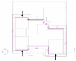
Turn off define slope in your option bar. You will see the slope symbol disappear from those edges.
Now select two edges at the north (bottom) you’ve just modified. Hold [ctrl] for add objects to your selection set, then click your edges. Activate move tool from ribbon.
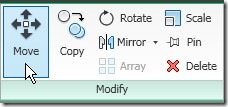
Click any where on your screen, move your pointer down. Type 300 then [enter]. This will add offset to these edges. Do the same with the other edge you modified. Move it to south for 300 mm. Click finish.
Let’s review our model in 3D view.
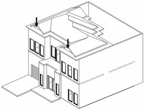
You can see there are gaps between your walls and roof shown by the arrows. Let’s fix this.
Select wall below the arrow, then click attach in your ribbon, modify wall group.
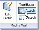
Select your sloped roof. Do this step for every wall below edges that we’ve modified.
If you want to add pattern, you can read this tip: Add pattern to your roof.
In the next tutorial, we will create roof slab edges.
*You can purchase this Revit tutorial compilation in an e-book. Find out the books in our E-Store .


Sir i need some models of concrete roof slab for a common resedential building in kerala
pls hw I will design my two bedroom.
another poorly developed lesson presented bythe inept .
you are in the wrong business , stay in the back room and draw .
shamefully there are many others who think they can teach and explain , however they are all sadly mistaken .
Can you explain what he did wrong in this lesson?
No offense big guy, but if you know something in this tutorial that he missed then at least post it.
Inept or not, tutorials are for people who are new to this. For every hot shot who thinks like you there are millions out there still trying to learn things.