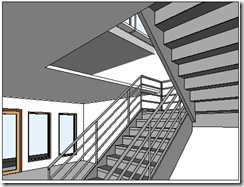
 We have created ceiling in our Revit model. Now let’s take a look to our void in stair area. There is a gap between floor at 2nd story and 1st floor ceiling. In the real world, of course this is not right. We have to close it.
There are several ways to do that, depends on your actual design. In this tutorial, we will add floor slab edge. But since the gap is too big, it can’t close all the gap. we are going to close the rest of it by creating custom ceiling component.
First thing first. We need to define what’s our floor slab edge look like. We are going to define it by creating a family.
From Revit menu, select new>family. Find Metric Profile-Hosted.rfa, and use it as template.
Let’s create a profile like this. You can use your own shape and size if you like.
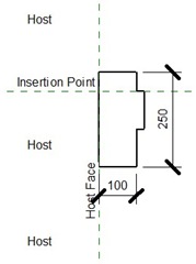
After you finish with this profile, save it. Give it a unique name so you can easily find it later.
Open the project that we’ve created. Load the profile to that project.You can do it from ribbon>insert tab>load family.
Now we are going to define a floor slab edge. Open 2nd floor plan, then activate floor slab edge tool.
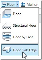
From contextual tab, activate element properties>type properties. Click duplicate button. Give it a new name.
For this type, change the profile to your defined profile.
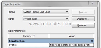
Click OK.
Now click on your floor edges at the void. You will see slab edges added. See this image below as your guide.
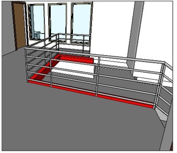
Who said 3D is difficult? :)
But it’s not done yet. We still have gap from ceiling to our floor slab edges.
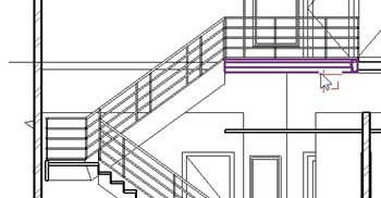
We are going to close it with custom component, a ceiling edge (I really don’t know what it’s name but I hope you know what I mean).
Let’s open 2nd floor plan again. make sure you have a section that cut the void. If you don’t have one yet, create it.
From ribbon>home tab select component>model in-place.
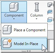
Revit will ask you, what is this family category? Select ceiling, and click OK. Give it name ceiling edge then click OK.
We are going to create a solid sweep. Activate it from your ribbon.
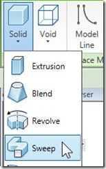
There are two components you have to create to define a sweep: path and profile. Let’s create path first. Click sketch path from your ribbon.
Create a path at your floor edge. You will see a dashed line with red point on it. That’s where you are going to draw your profile. If the dashed line is not in front of your section, drag it until you can see it on your section view.
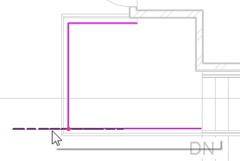
Click finish path.
By default, contextual tab will open modify profile. Click edit profile on that tab. Revit will ask you a question: which view do you want to use to draw your profile? Select your section view, click open view.
Now, draw your ceiling edge profile. draw a closed profile, similar too this. If this one looks too ugly for you, create it as you like, as long as it close all the gap.
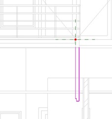
Shouldn’t sweep profile and sweep path coincident? Apparently not. My path doesn’t coincident with my profile, and it still works :)
Click finish profile. Click finish sweep. Then click finish model. That’s the object hierarchy. Inside your model, you have a sweep. Sweep is created from a profile (and path). Your need to click finish several times to end this.
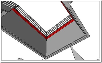
Now take a look to our floor slab edge and ceiling edge.
*You can purchase this Revit tutorial compilation in an e-book. Find out the books in our E-Store .


hEY! floor plan again. make sure you have a section that cut the void. If you don’t have one yet, create it.
How long does it take to replace the fascias on a semi detached property?
Thanks Edwin – just what I was needing to do – in your notes you mention you don't know what this cloor edge closer is called. In UIK we might call that a 'Haffit' … soffits are horizontal and haffits vertical. It's a nice word anyway. Best regards from Scotland.
Hello I wonder if you can help me. I am trying to draw a slab edge in Revit 2013 without much success.
If I use floor drop down menu and choose slab edge tool I get following error message when I click on edge of slab: Error, one element is inside another.
(incidentally I there is no sketch mode in this command. Why is that?)
I know some would argue they key that the profile dimensions have to be adjusted so that the thickened edge appears outside the main slab. How do you do this? Also does the edge have to be hosted in the slab family profile? How do you do this?
Thanks in advance.
hello from istanbul.. -revit-
i wanted to ask you about slab component( put marble finishes) in 2d section i can see that finishes but . i want to see in 3d also( for exaple i want to make terrace slab. and i want see marple with tickness.. is it possibe
Muzaffer,
There are several things you need to set. In 3D models, if you want to show the pattern in shaded view, then you need to configure the pattern using model lines. This roof tutorial should give enough explanation.
If you want to show the marble pattern in rendered images, then you need to setup rendering material.