In this Article...
We have created a very simple table as Revit family. As you suspect, it’s not that different using parameters in Revit 2D profile and Revit 3D families. When you begin to create complex Revit family, with more solid/void objects to handle, then you need to create a reference planes/lines to minimize the parameters number. It is also easier to manage.
Let’s take a look at this truss as an example. I created this truss with several sweeps (You can download it if you want to see it). I need to use reference planes to control the truss size and angle. We can’t do it just using angle and distance parameters.

Let’s get started.
Create a Profile
Why are we creating a profile again? We are going to create several sweeps. Instead of drawing the profile every time, we are going to draw it once, as a profile family. We can use it later when creating our sweeps.
Create a new family. Use Metric Profile.rft as a template (or without metric in template name if you use imperial). Draw a 30×30 rectangle like this.
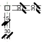
Pay attention where I put the insertion point. You may put it in different position, but remember that one of the edge midpoint have to touch the insertion point.
Save it. Give it a name like ‘baluster panel profile’ or something else you like. Don’t forget where you save it (I often forget my file location, so basically I try to remind myself).
Creating Baluster Panel
Defining Planes
Create a new family again. This time, use Metric Baluster-Panel.rft as a template. Yes, we are going to create a baluster panel, which we will use to assemble a railing later.
The template already has several reference planes. But we will add three more.
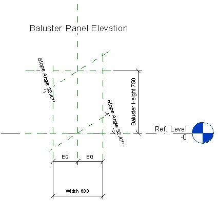
Activate reference plane tool.

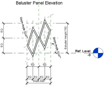
Draw more horizontal and vertical reference planes like this. Don’t forget to add dimensions, and constraint them to be in equal distance.
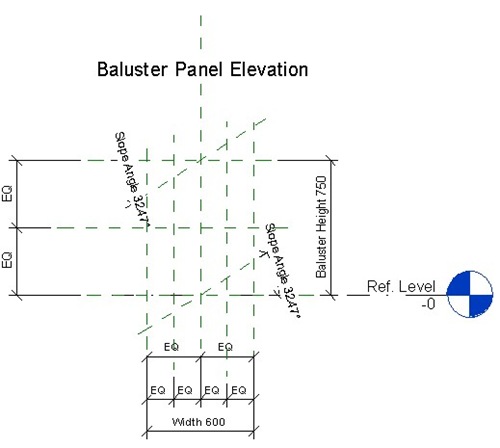
Now we have to add one more reference plane to anticipate when this panel is placed in stair, and have angle. Add a reference plane, make sure it’s snapped to the planes intersection at the center of this panel. Make sure it’s snapped before you click to define the point.
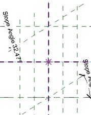
Move your pointer and make sure you create a parallel line to the slope plane. You should see the parallel symbol on your pointer.
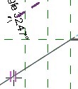
Press [esc] several times until you see the active tool now is modify tool. Click the last plane, and drag the plane end until they have about the same length with the slope angle plane.
Add an angular dimension (it’s on detail tab) to define the angle between the last plane and the mid horizontal plane.
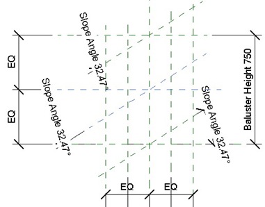
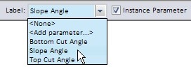
After you add the angular dimension, select the dimension and change it to slope angle.
Change the parameters value to see if it works as expected.
Defining Sweeps
Now activate the sweep tool. On Revit ribbon, click the small arrow below the solid button, then select the sweep button from drop down menu.
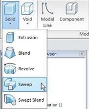
Now we are in sweep creation mode. We need to create a sweep path first. Click the sketch path from your Revit Ribbon: sweep contextual tab, mode panel.

Revit will ask you in which work plane you want to work with. OK, this is a tip how you can select the work plane by name: Select the work plane, and you should see the plane in blue rectangle in your screen. If you only see blue line, then change it to another work plane until you see the rectangle.
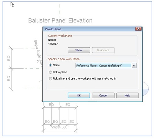
Click OK.
This is important:
Our sweep path will respond to the reference plane changes when we change the parameters. We want this path to stick to the reference plane intersections, so make sure you snap the line to the reference plane intersections. Press [S] then [I] to override your snap mode to point intersection mode.
Make your path like this. Then click finish path.
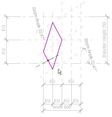
Now pay attention to the line with red dot, perpendicular to the path. That’s where we supposed to draw the profile. Can you imagine how difficult to do it?
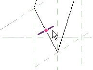
But don’t worry, we can use the profile we created before!
Click select profile from your Revit ribbon.

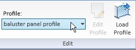
Now from your Revit ribbon, select the profile you’ve created before. Of course, if you haven’t loaded it, you need to load it by clicking ‘load profile’ first.
You may need to see how the profile is placed in 3D view. Make sure the profile lies inside the closed path. You can change the angle and/or flip your profile using option bar.
![]()
Tips: try to use 90 deg or 270 deg. You may want to make sure by seeing it from 3D view or other elevation views.
Click finish sweep.
Create another sweep like similar like we created before. Finish the baluster panel like this.
You can see the baluster in 3D like this.
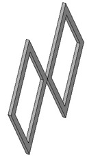
Don’t forget to ‘flex’ the model by changing the angle and height to see if it works!
After you finish, change the Baluster Height to 500, and Width to 400. You can download and compare mine to your panel here.


Hi,
when i make the slop angle parameter for new central inclined plane, it shows the planes are over contrained.
when i would like to change width and height to flex model, then also i get wrong message.
det er underlig at plane oversettes til fly her, da det er et adjektiv rett oversettelse skulle vel da være: overflate nivå