The named fence option allows the user to create a permanent fence within the MicroStation file for reference file clipping.
A common theme among sheet creation is that a user will cut a sheet at the beginning of a project and attach the appropriate reference files then later on down the road will add more reference files to the sheet.
Each time a reference file is added to a cut sheet a new fence is placed and the file clipped. When you highlight all the reference files you will see many clip boundaries in your file and they will not match the previous fence clips.
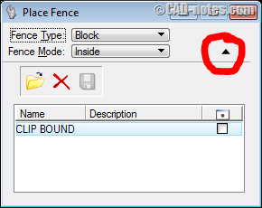
A cleaner way of clipping reference files is using the Named Fence option. To activate the Named Fence option, select the Place Fence tool, select the correct Fence Type and Fence Mode, place your fence then select the down arrow in the Place Fence dialog box.

When the fence is placed, the computer disk icon will become active. Click on the computer disk icon and key-in a name for your fence E.g. CLIP BOUND.
Dismiss your fence and then click on the toggle next to the newly named fence; you will now see a MicroStation element appear in the same place as the fence was placed.
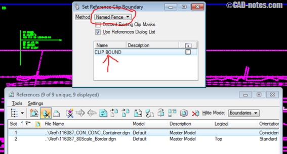
Once the fence is named you can now use it for clipping your reference files. Select the reference files that you want to clip in the reference file dialog box, select the Clip Reference option and then select the Named Fence option from the pull down and highlight the named fence I.e. CLIP BOUND, click anywhere on the screen to complete the clip bound operation. You do not have to toggle on the named fence to clip your reference file, you can keep it toggled off because MicroStation knows that a named fence is there even if it’s not displayed.

Using named fences eliminates constant fence placements for clip bounding or multiple shapes on scratch levels leaving your MicroStation file clean from unwanted graphics and one step closer to a cleaner deliverable for your client.
If after you created your named fence and you have to modify the limits, select the Place Fence tool, toggle the down arrow and toggle on the named fence that you wanted. Once the named fence is toggled you will see a MicroStation shape element. Once this shape is displayed you can modify it with the basic MicroStation tools. You can modify the shape to lengthen or shorten the reference boundary, you can add vertices to the shape, you can move the shape, you can do whatever you want to the shape.
As you modify the shape, the reference file boundary will update dynamically. Once your shape (reference file clip boundary) is as you want it, toggle off the named fence so that the shape disappears. Keep in mind that this is a true MicroStation element and if left on, it will plot. I recommend that you change the shape to a no plot level just in case the shape is left on.
If you add more reference files in the future all you need to do is select the reference file(s) that you want to clip in the reference file dialog box, select the Clip Reference option and then select the Named Fence option from the pull down and highlight the named fence. Also, you can have multiple named fences for one file, such as a detail sheet referencing many different details, you just need to select the proper named fence for the proper reference file.
More tips
To quickly match an existing elements symbology, follow the two options below.
1. Drag element to match – To match an elements symbology, simply select the element with your selection pointer and drag the element to the Active Level pull down (shown below).

2. Alt + Data – To match an elements symbology using your mouse, hover the mouse pointer over the element and press Alt + data (mouse data point button).
Acusnap for Fence Placement
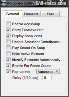
If you are one who relies heavily on automated snapping by using the multi snap and AccuSnap toggle (as shown below) you may have found it difficult to hover over any shape or element and snap to it to place a fence..

To remedy this, go to Settings>Snap>AccuSnap and in the window that appears toggle on “Enable For Fence Create”. This will allow automated snapping for fence placement.


