Autodesk® Inventor® Tube & Pipe has a time saving feature built in to the routing tool: Auto Routes. Auto Routes are generated when a user selects the start and end point of a pipe route. Inventor calculates possible solutions to the route given the points selected and any rules in place with the current tube & pipe style (eg. min or max segments, allowed fittings etc). It appears on the surface to be a slick, neat and clean time saving feature…. Until you try to make a change.
Designs are like living beings, they change constantly. Equipment is changed, moved, deleted. Pipe styles change, line sizes are modified… etc. Your piping designs need to be able to adapt to these shifting tides, and in my opinion Auto Routes just can’t do that very well. In the images below I show, first a route created using Auto Route. Next is the route populated, and finally… what happens if I move the pump back 16”.
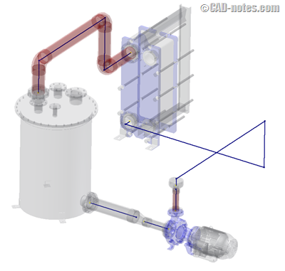
In this view we see the route I selected from 4 possible solutions using Auto Route. Right away I notice that the short legs appear to be too short, but for this demonstration I will let that go. I have 5 segments which appear to be perpendicular to one another, and as laid out, this route does get the job done… more or less. Now let’s populate it with pipe and fittings.
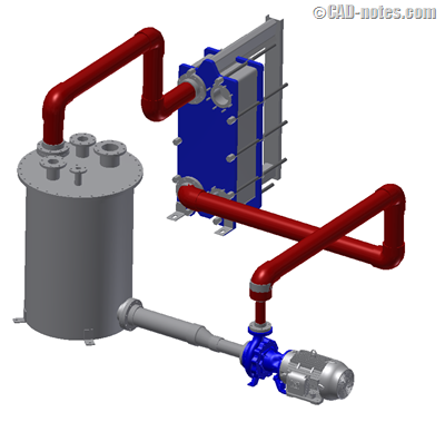
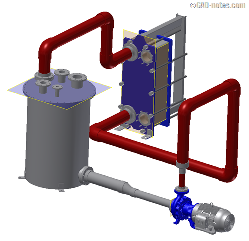
As shown above, the route populates ok, although we can now see for sure that the connection segments at the pump and heat exchanger are way too short. Again, I’ll let that go for now. So, let’s make a design change, and see what happens. Let’s move the pump back 16” and see what Auto Route does with this selected solution.
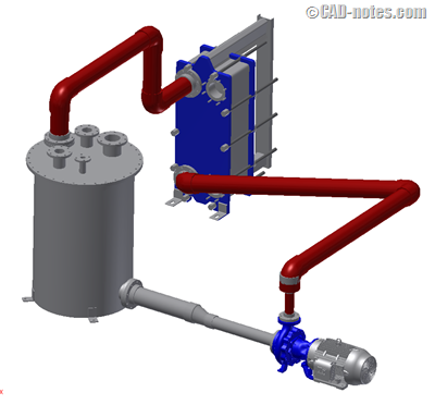
As you can see, Auto Route has changed the number of segments, as well as the angles of this route. I am going to show you an alternative way to do this, which will leave you with a route that is fully constrained, yet flexible enough to keep up with design changes you may make to the equipment or routes surrounding it.
Let’s look at the original route sketch again, and how to change from an Auto Route to a conventional sketch.
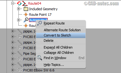
To convert the Auto Route, locate it in you model browser, as shown, and select Convert to Sketch. The route will now have dimensions and constraints on it. I want to show you how to fully constrain this route with only 2 dimensions, and leave it in a state where it will easily adjust to the same change in the pump location that we used in the earlier example.
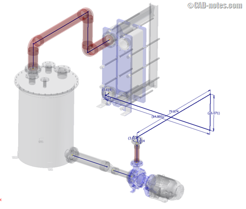
First we will need to modify the two shortest dimensions so that the elbows will actually fit when the route is populated. For this demonstration, these will actually be the two segments whose length I would like to control with dimensions. I will set these two dimensions to 36”, and delete all other dimensions.
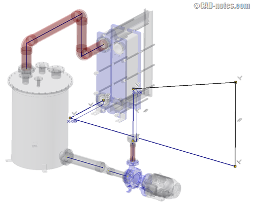
You can see that by changing these dimensions, the route has gotten a little out of control, don’t worry… we’ll fix it. Next I will delete all parallel and perpendicular constraints that were placed by the system, (except for those at the two end points, we want those to remain perpendicular to the connection point) and replace them with my own, using projected work planes to lock down the direction of the other segments.
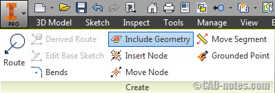
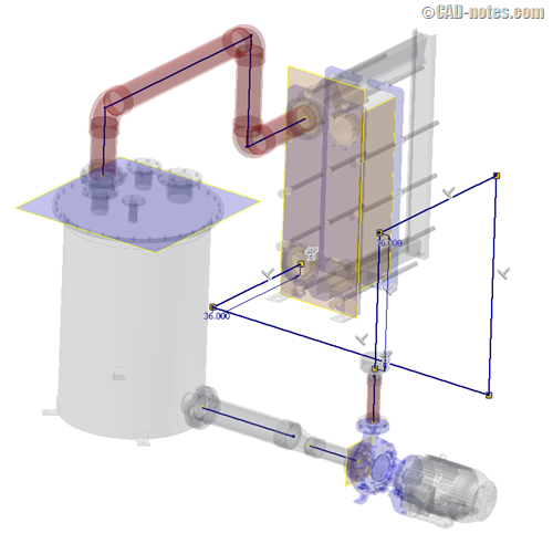
Select the Include Geometry tool from the Route panel on the ribbon above. I like to use work planes, since they give me a lot of freedom and control. I will select the top of the tank lid, and the front and side panels of the heat exchanger… creating work planes on those surfaces to allow me to place perpendicular constraints in three directions to lock down this sketch.
I place a perpendicular constraint on each of the remaining legs, to whatever work plane makes the most sense to the direction I want it to go. Now the route has nice clean 90° angles, and only 2 dimensions.
Let’s look at the result populated now.
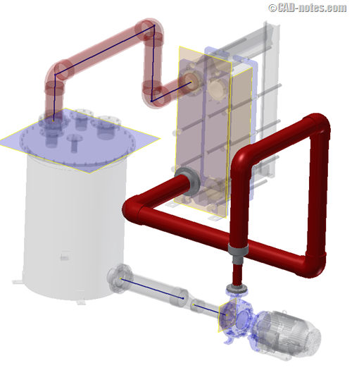
This is more of the route I had in mind for this pipe line. Very similar to the result given to me by Auto Route, but now I have full control over its behavior if other design parameters should change. (And we all know they will.) To demonstrate this, let’s move the pump back 16” like we did earlier and view the results to this route.
The route stayed essentially the same, with the segment that I left intentionally un-dimensioned growing to meet the new location of the pump. If the heat exchanger were to move back as well, the top segment of this route would also grow to accommodate that change.
So there you have it. Don’t trust Auto Route to behave when you make design changes such as these. Tank control of your route sketches with work planes, and strategically placed dimensions and constraints. The results speak for themselves, I think.
Enjoy!


Good article Chris.
It does make you wonder what advantage tube and pipe has over just creating an inventor assy consisting of
content central parts which can be rotated,constrained,extended etc.
Tube and pipe does seem to be a slow laborious process particulary when things have to be altered, i suspect
that the system was perhaps designed by persons with little knowledge of process piping and the consequences of having to modify pipe runs when major components need to be repositioned, however i will
persevere and eventually with the help of your article and others master the confusion and the illogical approach that so many modern cad systems seem to adopt.
Hi Martin
Tube & Pipe can be quite frustrating, believe me. Recently I did a little experiment when I was having trouble with a particular pipe line. I tried building it with CC parts and pipe spools dropped in from the CC aswell, and just using fitting connect, or standard constraints. Turned out to be an even bigger pain. I think, for me, the path is to continue to work with T&P, subvert the rules wherever I can, and continue working with AutoDesk to impliment improvements to the program. Thanks for reading and stick with it!
Thanks , very good info!
This is so special and interesting i see structures of this kind at our newly opened mine