In this Article...

Another parametric feature available is dimensional constraint. We discussed about geometric constraint, and this time dimensional constraint.
Dimensional Constraint Types
Basically we use dimensional constraint to maintain distance between points or objects. Usually dimensional constraint don’t work alone. We use geometric constraint along with dimensional constraint.
There are three types of dimensional constraint:
- Dynamic Constraint
- Annotational Dimension
- Reference Constraint
Annotational Dimension
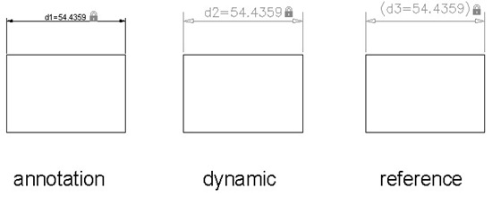
In a nut shell, annotational constraint behave like common dimension we know all these years. You can plot it, you can assign it on a layer, and the size behave like other annotation. The size is not affected when you zoom the drawing.
Dynamic Constraint
Dynamic constraint is a bit different. it’s only for display purpose. It will not be printed. If you remember how you use parameter in dynamic block, it also display at the same size when you zoom the drawing.
You can change the form, dynamic or annotational by changing the ‘form’ variable.
Command:
DIMCONSTRAINT
Current settings: Constraint form = Dynamic
Select associative dimension to convert or
[LInear/Horizontal/Vertical/Aligned/ANgular/Radial/Diameter/Form] <LInear>:F
Enter constraint form [Annotational/Dynamic] <Dynamic>: A
Reference constraint
Reference constraint is not created directly. You can create a dynamic or annotational dimension, and then convert it to reference dimension.

We use reference constraint only for showing the distance values. We can’t change the parameter like dynamic or annotational constraint. Let’s compare them.
Annotation constraint size will follow the object size when you zoom. Dynamic constraint will show the same size, no matter how you zoom it. The reference dimension is shown with brackets.

Using Dimensional Constraint
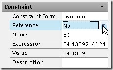
After you placed dimensional constraint, you will see the parameter name like d1, d2… dia1, dia2… by default. We can change it later. You can change the parameter by selecting the constraint, right click your mouse above dimension, and select edit constraint.
Or you can change the name and value in properties palette.

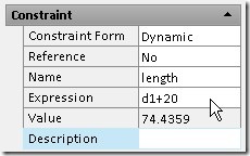
We can input calculation in expression field. For example, we want the base length is dependant to body length plus 20mm clearance. This workflow is used heavily in manufacturing design.
By using dimensional constraint, we don’t modify the object. We change the parameter value, and the object will be adjusted. To make the result predictable, we use it together with geometric constraint. We will create some objects using these parametric behavior later. But that’s the concept.


