In this Article...
In the last Revit tutorial, we have discussed how the workaround to create a siding wall, in 3D. That was probably a cool way to do it. However, when you design a complex building, you probably want to avoid too many 3D objects. Especially if your workstation can’t handle a large model. This is an alternative way to create a siding wall in your Revit model, by using Revit drafting tools and defining the wall materials.
Defining Surface Pattern
To Show the Siding Wall Pattern in Elevation Views
Before we go to the Revit detailing tools, let us find out how we can represent the siding wall in elevation views.
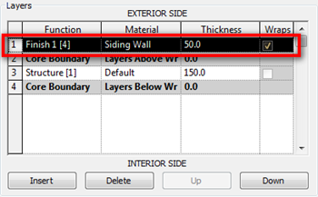
This trick is easy: we need to create a new material and define the surface pattern. You can use available horizontal patterns or simply create a new one. Remember to use model pattern if you want to show it in 3D too.

We apply this Revit pattern to the wall structure, as the exterior finish.
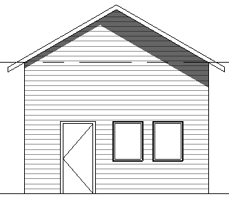
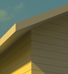
This will give us result like this. This should be close, except for the side.
To Show the Siding Wall Pattern in Photorealistic Rendering
We can see the pattern in shaded/hidden lines views, but not in photorealistic rendering. To see the siding pattern in rendered views, you need to change the wall material in render appearance tab. Find something like siding finish. If you have a scanned image or picture taken from your digital camera, you can use it too.
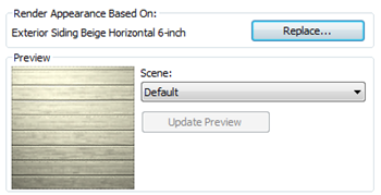
This is the render result, taken directly from Revit without further touchup. Not bad, I guess.
Creating the Detail Repeating Detail
Now we can see the pattern in elevation view and in photorealistic rendering. However, when we create a wall section, there is no siding details!
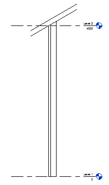
We can always add the details in our Revit views later. Revit has some tools for further detailing, when it’s impossible to add the information in 3D model. Or when we think it’s easier to detail it in 2D.

What we create using Revit drafting/detailing tools will only be visible in that particular view. They will not be visible in any other view, and don’t have relations to the 3D model. So you probably want to do this step after you are sure you are not going to modify the model anymore. The Revit tool that we are going to use is repeating detail.
Creating Detail Profile
Before we can create the repeating detail, we need to create the detail profile first. Create a new Revit family using template: Metric Detail Component.rft.
Activate masking region.

Create a profile like this. This is your siding profile. Use your own size for this profile.
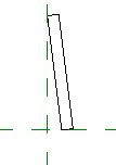
Add two more profile like below (click thumbnail to enlarge).
But before you start to create them, change the line style to <Invisible lines>.

What are we doing? Why not using lines? The masking region will mask everything exist on your Revit view. We need it to cover the exterior wall layer.
Save the file and load it to project.
Creating and Using Repeating Detail
Create a wall section and open the section view.
In your Revit ribbon, annotate tab, detail panel… click component>repeating detail.
You will have the contextual tab opened. From your Revit ribbon, access Element Properties>Type Properties.
Change the detail to the profile you created before, and the spacing value. You need to define the spacing based to your profile size.
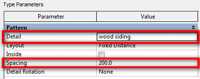
Click OK, and now we are ready. To place the repeating detail, you need to define two points, just like when you draw lines. Place the first point at the bottom of your wall core, and the second at the top of your wall.
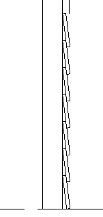
If you have difficulties, you can download this profile that I use in this post. This animation also may help to see how it works.
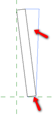


Mahalo for uploading Edwin. . . but i do not understand your process. . . You say add 2 more below . . . below where? Please articulate as this doesn’t make sense to my wee brain.
They are 2 blue triangles that are used as the mask. Refer to where are the red arrow pointing.
Well done, I´ve learned a lot with your tutorial, tnx!!!!
http://www.youtube.com/watch?v=n6p8YSZskeE