We learned how to place plumbing fixture. In this tutorial, we will learn how to create a pipe route. There are several ways to do this. In this tutorial, we will cover how to create a pipe route manually and connect the plumbing fixtures to the pipe route.
Open your exercise file and open 1 – plumbing view.
Load and Replace Urinal Family
We used a loaded family in our project template (M_Urinal – Wall Hung). But it doesn’t have a connector for water supply. We will replace them before we continue. Go to Systems tab, click Plumbing Fixture.

On the ribbon, mode panel, click Load Family.

Under US Metric library> Plumbing> MEP> Fixtures> Urinals select M_Urinal with Wing – Wall Hung.rfa. Click open.
Click Modify on the left most of the ribbon.

Click and hold your mouse left button, drag to select all urinals.
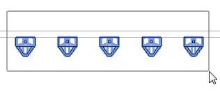
With all urinals selected, select the new urinal from Type Selector. It’s on Properties Palette.
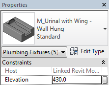
Notice that this urinal has default elevation 430 from floor level. We will accept this value. Now all of the urinals are changed to the new type.
Creating Pipe Route
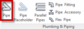
Activate pipe tool. You can find it on the ribbon> Systems tab> Plumbing & Piping panel.
On the options bar, change the diameter to 40 mm and Offset to 2750 mm. It means the pipe will be created 2750 mm above the floor level.
![]()
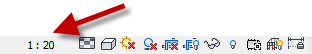
Before we continue, change the view scale to 1:20. You can find the scale selector at the bottom of your view. We change this to allow us to see the route easier.
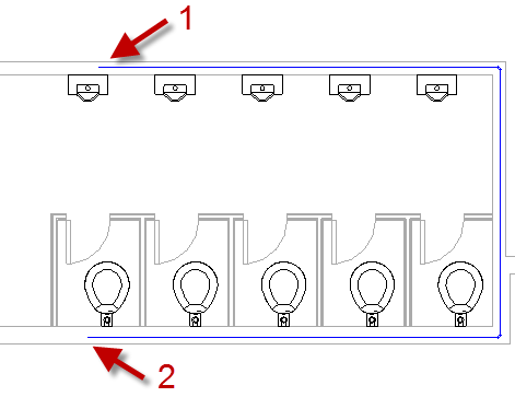
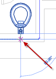
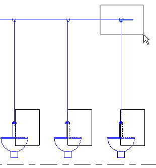
Draw the pipe inside the walls like shown below. Start from before the last urinal and end after the last water closet. We do this on purpose, to see different methods to modify the pipe route.
With the pipe tool active, change the pipe size to 50 mm and elevation 2750 (same as the previous pipe).
![]()
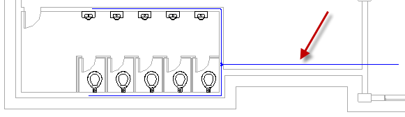
Add the pipe from the existing route to the next room.
Connecting Plumbing Fixtures to Pipe
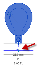
Let’s start with the water closet. Click modify tool then select the right most water closet.
You will see the connector symbol for water supply. Click the symbol to create a pipe.
If Revit asks you to select a connector, select Connector 1: Domestic Cold Water: Round: 25 mm @ 688 : In.
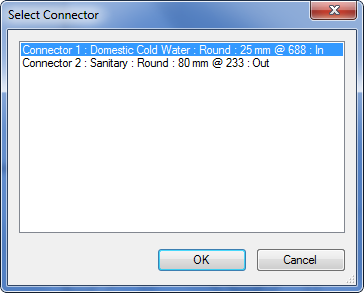
This water closet has two connectors. This time, we want to connect it to the water supply.
The pipe automatically starts from the connector. Click on the existing pipe to draw the pipe. Repeat the procedure for all the remaining water closet.
Notice the pipe exceed the last water closet. We need to trim the pipe.
Creating a section
We need to open another view to allow us selecting the vertical pipe. Let’s create a section.
Go to View tab, Create panel. Click Section to activate the tool.
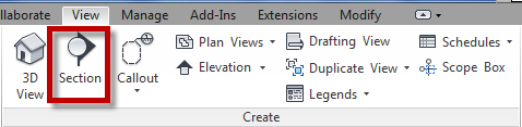
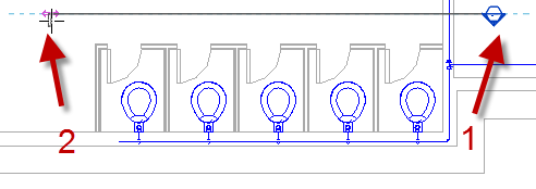
Click the start and end point as shown.
Press Esc to activate modify tool. Select the section then right click. Choose Go to View from the context menu.
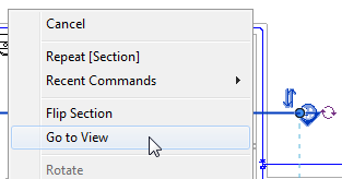
The section view is displayed.
Temporary Hide the Linked File
We will hide the architecture model first because it can interfere with our selection. Click modify tool then select the Revit link model.
Hint: you can select the window, floor or any architecture object to do this.
Press HH to hide the object.
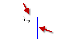
Now select the excess pipe and the tee like below. Press delete key.
On Revit ribbon, go to Modify tab> Modify panel and click trim/extend to corner.
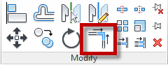
Select the horizontal and vertical pipe to connect them.
Press HR to restore the hidden element.
Go to 1 – plumbing view to examine the pipe. Double-click the view name from Project Browser. Notice that Revit adds an elbow at the corner.
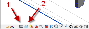
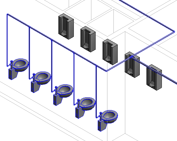
Now go to 3D view and examine the pipe route. Change the detail level to Fine (1). It allows you to see the pipes in 3D. Change the Visual Styles to shaded (2).
We will continue our pipe route in the next tutorial.
To Sum Up
In this tutorial, we learn:
- How to load Revit family
- How to replace plumbing fixtures with another family
- Create pipe route
- Connect equipment to pipe route
- Create a section
- Temporarily hide object and restore it
- Modify route with trim/extend to corner tool
- Change view detail and visual style.
Having Problem Following the Instructions?
You can see this video as a guide.
Or view it on YouTube: Revit MEP Basic: Creating Route and Using Connector


thanks for this awesome tutorial.
Hello, when I try to create a pipe., I encounter this problem. plz Help.
Warning
None of the created elements are visible in Floor Plan: Plumbing View. You may want to check the active view, its Parameters, and Visibility settings, as well as any Plan Regions and their settings.
You need to check the visibility settings and see if the objects are checked. You may need to check the Filter tab and see if your plumbing is enabled in this view.
Hello, when you place the pipe at 2750 it actually places it on the floor above.
Thank you for the input Matt. I missed that when writing this tutorial!