• Home
  • Training Books
  • Subscribe to Our Email Newsletter
  • About
    • Contributors
    • Feedback
    • Contact
    • Privacy policy
    • Cookie Policy

CADnotes

CAD Tutorials and Best Practices for professionals and students

  • Featured
  • AutoCAD
    • AutoLISP
  • Revit
    • Revit Architecture Basic
    • Revit MEP Basic Tutorial
  • Inventor
  • MicroStation
    • MicroStation Basic Tutorial
You are here: Home / MicroStation / MicroStation tip: using active element priority

MicroStation tip: using active element priority

May 2, 2011 by Edwin Prakoso Leave a Comment

In this Article...

  • Preparing the bottom objects
    • Set the priority
  • Creating the top object
  • See it in action!

Bentley Systems introduce active element priority since MicroStation V8 XM. This feature can be very useful. I believe many MicroStation users may overlook this feature.

We can use it to make sure an element always behind the others (or always on top). If you want to use an image as underlay, then we can set the element priority as low as possible.

In this post, I would like to try using it to automatically ‘change’ line type when they are ‘hidden’.

The idea is to create two layers of elements. The first one, lies at the bottom. It uses continuous line. The second one is identical object. Created on top of the first one, uses hidden line.

Because we have the continuous line as underlay, we see it as continuous line. But when we created new object with priority between those two, will cover the first object and show only the 2nd one. It means that part will be shown as dashed lines.
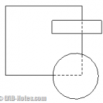
Confused? Let’s try it.

Preparing the bottom objects

I created two identical rectangular using block tool like below. One rectangular uses line style 0 (continuous) and the other uses line style 2 (dashed).
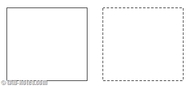
rectangulars

Both rectangular were created without fill. If you use fill, then it won’t work.
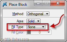
place block options

Set the priority

Now let’s set the elements’ priority. Open element information dialog.

element information

Select the continuous rectangle, change the priority to negative value. For the dashed rectangle, change the value higher. I use –5 and 5 for them.
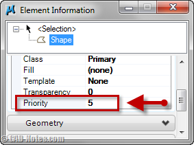
element information dialog

Now move the rectangle so they are overlapped each other. You should see only one continuous rectangle now. You may want to group them together, to make it easier to manipulate later.

Creating the top object

Now let’s create another rectangle. This time with fill. Use 255 as the fill color.
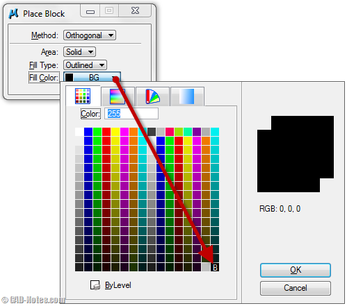
block with fill

Draw the rectangle to cover some part of the first rectangle. Now every time you create a closed polyline above the first rectangle, the covered area will be shown as dashed lines!

When you move it, the dashed lines will update the location. Uhm… at least it looks like that!
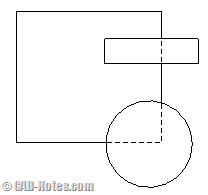
hidden lines

See it in action!

If you’re still not clear the steps above, try to see this video.

Automatic hidden lines with element priority

Do you think it will be useful?

About Edwin Prakoso

I work as a Sr. Consultant in PT Cipta Satria Informatika. I've been using AutoCAD since R14 and Revit since Revit Building 9. I occasionally write for AUGIWorld magazine and I am also active in Autodesk discussion forum. I'm a member of Autodesk Expert Elite, an appreciation for individuals who give contributions to the Autodesk community.
Connect with me on twitter or LinkedIn.

Filed Under: MicroStation Tagged With: element priority, hidden element, MicroStation Tips

0 0 votes
Article Rating
Subscribe
Login
Notify of
guest

guest

This site uses Akismet to reduce spam. Learn how your comment data is processed.

0 Comments
Inline Feedbacks
View all comments

Featured

AutoCAD Toolsets Tutorial – Get the Best of your Toolsets!

Autodesk released AutoCAD 2019 with seven toolsets. They are good software and can help your design process. But where can you can find the tutorials? It is a big step if you only use AutoCAD before!

Recent Articles

  • Autodesk Construction Cloud Activity Log
  • Exporting AutoCAD Plant 3D Model to Navisworks
  • Autodesk Data Connector for Power BI is Now Available

Advertisement

New on CADnotes

  • Autodesk Construction Cloud Activity Log
  • Exporting AutoCAD Plant 3D Model to Navisworks
  • Autodesk Data Connector for Power BI is Now Available
  • Autodesk Forma Design Contest
  • Revit 2025: Toposolid Enhancements

Meet the Authors

avatar for
avatar for
avatar for
avatar for
avatar for
avatar for

Get Connected

CADnotes on FacebookCADnotes on InstagramCADnotes on TwitterCADnotes on YouTube

© 2009 – 2025 CADnotes · Feedback · Privacy Policy · Become an affiliate

wpDiscuz