If you work with the metric unit, you usually work with millimeters. At least the default template available is in millimeter. However, sometimes it makes more sense if you show the dimension in meter. For example, when showing building dimensions, many people are more comfortable to see it in meter.
We will show you how you can draw in millimeter but showing the dimension in meter.
Working with Dimension Style
You can change the settings in the dimension style. Type DIMSTYLE then press Enter. Select your Dimension Style then click Modify.
Changing Scale Factor
In the Primary Units tab, Measurement scale group, change the Scale factor to 0.001. It’s the conversion factor from mm to m.
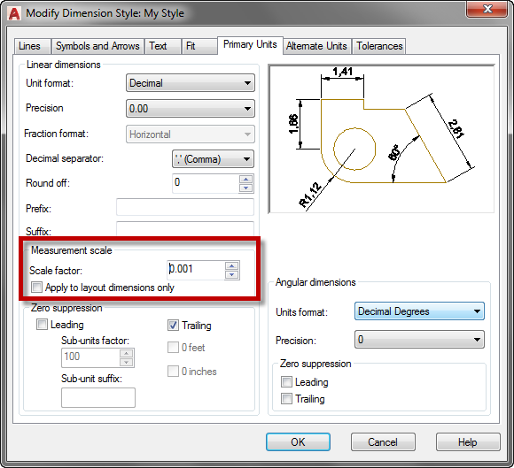
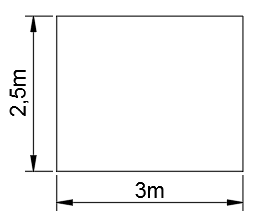
Now when you draw 3000 in your drawing, the dimension will show 3.
Using m as Suffix
You can add m as the dimension suffix.
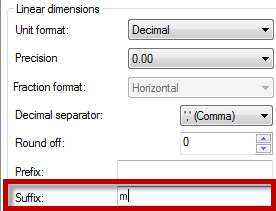
It means you can see m at the end of your dimension value.
Adding m as Decimal Separator
Now let’s take it a bit further. Can we show 2m50cm or 1m25cm instead of 2.5m or 1.25m?
You can use m as decimal separator and limit the decimal number to 0.00. Because if you want to show in cm, you only can show two decimal digits.
First, let’s open the Dimension Style again.
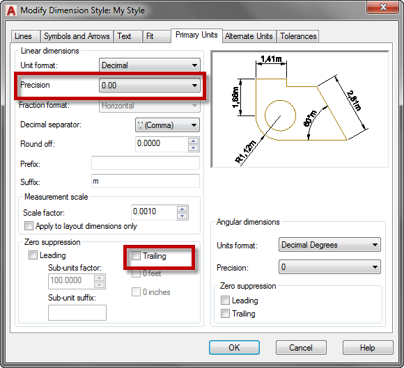
Make sure the Linear Dimensions> Precision is 0.00.
Turn of the Zero Suppression> Trailing. By turning off this option, the two decimal numbers will always show even they are 0.
If you check in the Decimal separator list, you only can choose period, comma, or space. You can’t type a custom separator. But there is a workaround.
Close all dialogs then select a dimension. Press Ctrl + 1 to open Properties Palette.
In the Properties Palette, find the Primary Units category. In that group, change the Decimal separator to m and change the Dim suffix to cm.
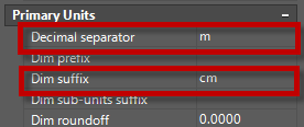
Now you can see the dimension changed.
Creating Dimension Style from an Existing Dimension
However, we only change appearance for one dimension. We want to make a dimension style from that dimension.
Select the dimension then right click. In the context menu, choose Dimension Style> Save as New Style.
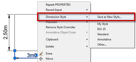
Now you can use it as a dimension style. All of your dimension will have two decimal places, m as decimal separator, and cm as the suffix!
The Instruction Video
You can also watch how to create and use the dimension in this video.


HI ,
WHY SCALE FACTOR IS TAKEN AS .001
Hello,
In Germany, they use meters for dimensions larger than 1m and centimeters for dimensions smaller than 1m. So, for example, if I have object that is 515cm long, dimension should show 5.15, and if I have object that is 85cm long, dimension should show 85. Few things to note here: Units should not be displayed, and dimensions larger than 1m should have 2 decimal places and dimensions smaller than 1m should have no decimal places. Can it be achieved with one dimension style in AutoCAD or not? I always create two dimension styles, but it is waste of time… All German programs have this feature built in, but I am struggling with AutoCAD…
Hello Milan,
I don’t think it’s possible to do in AutoCAD. If you feel it’s wasting time, I only can suggest you to define the two dimension styles in your AutoCAD template. And place the dimension styles in AutoCAD tool palette for a quick access.
thanks for explaining dimension styles in detail.
You can also use these features to show both Imperial units and Metric units in the same dimension line for those working in the United States.
Are you referring to the alternate unit?
Yes. The alternate unit would be Metric. The default setting would convert it to centimeters.