In this Article...
We covered how you can create your own AutoCAD customization file and add your own commands, panel and ribbon tab there. In this article, we will cover more details about arranging our tools in a panel and tab by working with their properties. How to make our panel looks as we expected.
We will add several more commands there, custom and AutoCAD default commands. If you haven’t got any custom command, you can follow our previous tutorial or just continue with default commands.
Adding custom commands
I created several commands from Paul Munford’s macro like below. You can refer to those macros or create your own if necessary.
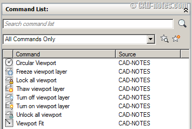
I’m too lazy to create proper icons for each command, so I just use default icons. Of course, as you can see, the circular viewport is the same with draw circle icon. It can confuse your team if you do this. In the real job, create custom icons for them!
Drag all the commands to our viewport panel. Arrange the sequence in logical order. I arranged mine like below. The top to bottom commands will show in panel from left to right.
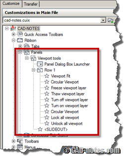
You might want to click OK, close the CUI dialog to see the changes. The ribbon panel should appears similar like below.
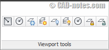
OK, the panel shows all command in one row, just like the old AutoCAD toolbar. This is not right. We still have plenty of space above and below it. We will add more rows to arrange them.
Working with rows
Open your CUI dialog again. We are still working with our own customization file.
Find your panel below ribbon category. Right click above your panel title, and choose new row from context menu. This will create ‘Row 2’ below your panel.
Repeat the process to create ‘Row 3’.
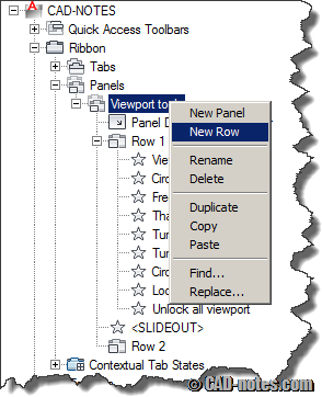
Place all the rows above <SLIDEOUT>. We will discuss about slide out later in this article.
Arranging commands in different rows
Now we have 3 rows in our panel. Drag and drop your commands to those rows. You can place similar commands on the same row. Below is how I arrange my commands.
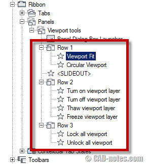
You can see on the right pane the preview of your ribbon panel now. It looks better, but you can see that there are empty spaces at row 1 and 3. It’s because they don’t have the same commands number on each row.
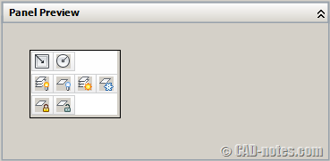
You can add more commands or move them to different row to make it looks neat. But this time, let’s adjust the appearance by change the command button width.
Adjusting command appearance
Let’s change the viewport fit button. Select it under your panel tree.
Change button style to Small With Text. You can see at the panel preview now the button is wider. But the text is too long, now it’s become longer than other rows.
Change display name to VPort Fit to make it shorter.
You may not see the changes immediately on preview panel. Change the button style to other style, then choose small with text again.
Do the same thing with the last row. Now my custom panel looks like below. It looks better, isn’t it?

Add default AutoCAD commands
There are some default viewport commands we can add here. I consider to add this viewport dropdown control. It will allow us to create different shapes of viewport, only with one button.
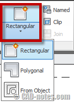
To add this button, in CUI dialog switch to all customization files. This will allow you to access all commands from all CUI files.
Change command filter to ribbon control elements. This action will filter the commands. There are still many commands available. To control it further, type viewport in search field.
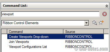
Drag create viewports drop-down to your panel.
Working with Sub Panel
Here is the thing: the create viewport drop-down is the common command that we will use often. So we want to make it standout from the crowd. We want to make it large. So change the button style to large with text.
But wait! This doesn’t look right. The large button should be on the left, using all three rows’ height. The other commands should be on its right.
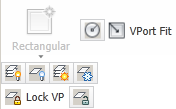
How to make it looks like this?

We need to separate the commands in a sub panel. A sub panel lets you to define the placement just like in different panel.
Right click above Row 1 and choose New Sub-Panel from drop down menu. You should see a sub panel is added, with one row. Add two more rows for the sub panel.
Move all custom commands from main panel rows to this sub panel. Leave the large button on the main panel.
After the rows are empty, you can delete them.
The final arrangement should be like this:
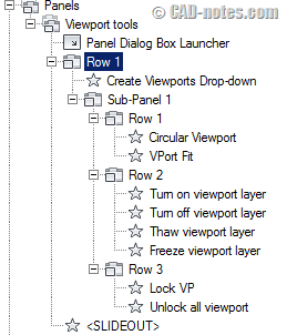
So our all of our custom commands are now on the sub panel, and the create viewports drop-down on main panel. You may want to play a little bit more by yourself about this arrangement.
About slideout panel items
Do you notice the <SLIDEOUT> item in your panel? Do you know what it’s for?
Let’s add one more row in main panel. Don’t create it in sub panel. If you do it right, you should see Row 2, not Row 4.
Add more viewport tools to that row. Choose any tools you want to.
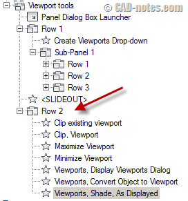
Check the preview and close CUI dialog by clicking OK.
So what does the slide out do? You will see small arrow pointing down at your panel name. Click it. Now you should see it slide out and show the second row!
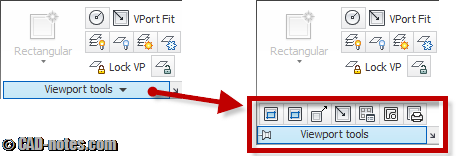
This is useful if you have more tools to place at your panel, but rarely used.
You may want to try placing your custom panel at existing tabs. Or playing around with more configurations. Feel free to do it. We created our own customization file, didn’t we?
Next, we will cover about creating menu and toolbar. Yes, even the latest AutoCAD by default using ribbon, many of us still use menu and toolbar!
How are you doing so far?


Wow nice info ‘n superb explanation Edo!
Sometimes to replace icons or ribbon component is something that is tiring but it should be done to speed up the working drawings. But if we often use different versions of the AutoCAD the commands used will be back again to its original position by using a keyboard or menu bar.