In this Article...
When creating a Revit model, we are often required to add details to provide information or make the model looks compelling. One detail that we constantly add is patterns (or hatches in AutoCAD).
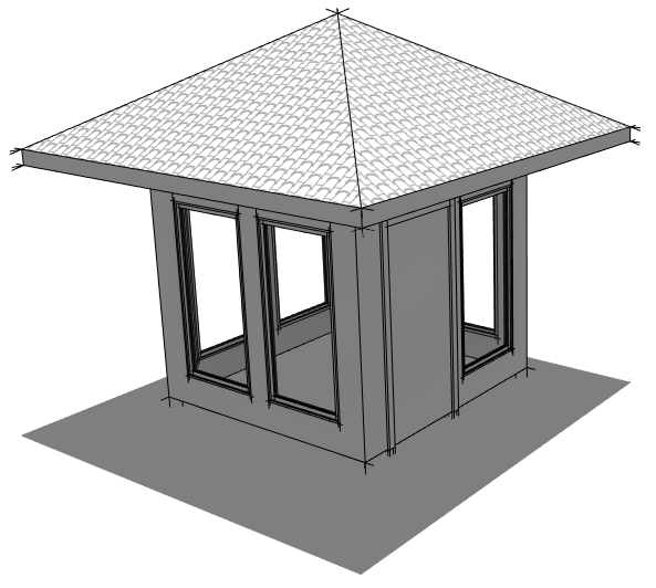
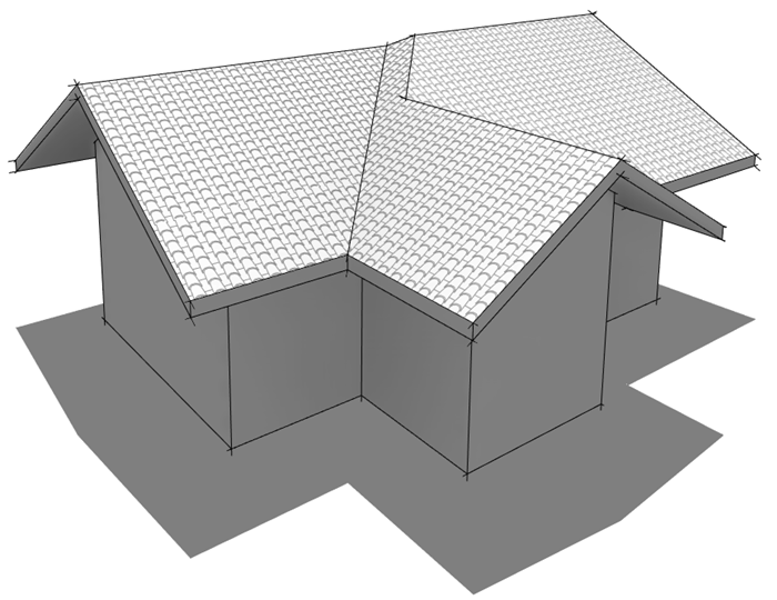
We will add a pattern for a Spanish roof like the image below.
Creating a Model Pattern
To create this roof pattern, you must have a roof model pattern. You can download the pattern file I use in this article here.
Drafting vs. Model Pattern
Revit has two types of patterns: drafting patterns and model patterns, and both seem similar. What is the difference?

Drafting Pattern
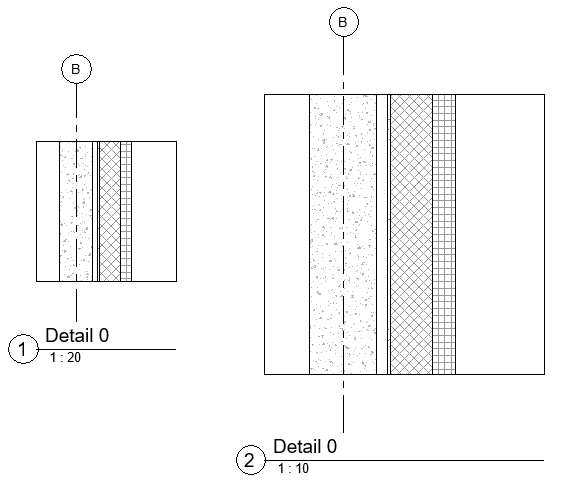
Drafting patterns are annotations. It means the patterns provide additional information to the model, but it’s not part of the model itself – for example, the concrete pattern or brick pattern in section views. Drafting pattern size will adjust the size consistent with the view scale.
The image below shows the same view in different scales. The patterns adjust the scale to ensure they are visible.
Model Pattern
Model patterns are the actual representation of our model—for example, floor pattern, ceiling pattern, roof tile, etc.
The view scale doesn’t affect model pattern size. Because the pattern size shows the real-world object size. 400×400 mm floor tile always shows as 400×400 mm.
AutoCAD Hatch Conversion to Drafting Pattern or Model Pattern
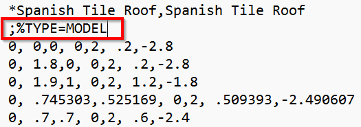
You can use AutoCAD hatch from a PAT file in Revit. But before using it, you need to add the following parameter in the PAT file.
For a drafting pattern:
;%TYPE=DRAFTINGFor a model pattern:
;%TYPE=MODELAdd the parameter immediately after the pattern name, like in the example below.
Importing a Custom Pattern
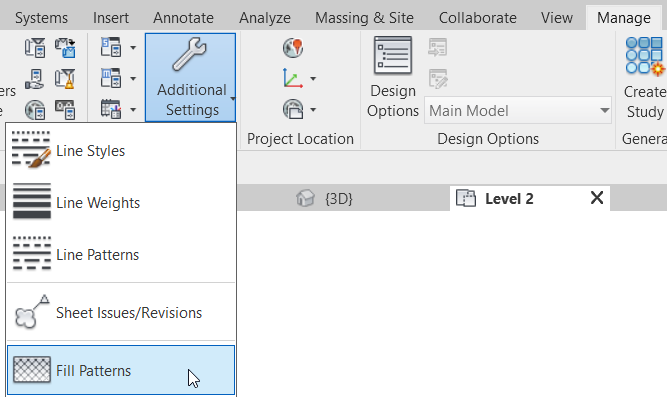
You can import patterns by accessing from the Manage tab> Settings> Additional Settings> Fill Patterns.
Select Model Pattern as the type, then click New Fill Pattern.
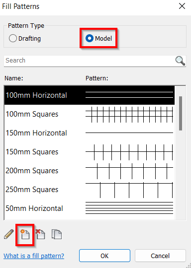
Define as follows:
- Revit will get the pattern name from the PAT file, but you can rename it later. Change the pattern type to custom.
- Click browse to find the prepared PAT file.
- Usually, hatch files are in the Inch unit. If you use another measurement unit, input your import scale here.
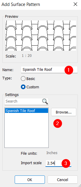
Click OK.
This roof pattern is defined.
Defining Roof Finish Material
We defined the roof pattern. Now we need to define the material and use that pattern to represent a roof material.
You can access the Material Browser tool in the Manage tab> Settings panel.
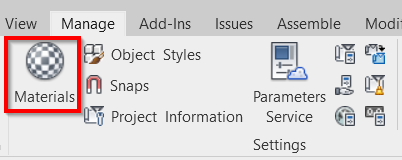
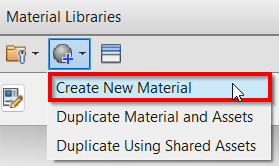
Let’s create new material for the roof. You can create a new material by clicking Create New Material at the bottom left of the Material Browser dialog.
In the Identity tab, rename the material.

In the Graphics tab, find the Surface Pattern category and Foreground subcategory. Click the empty box next to the pattern parameter, then choose the pattern that you created before.
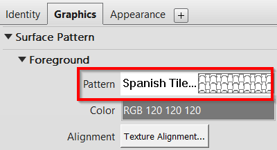
Defining Roof Family Type
The last step is defining the roof type. When you create a roof, click Edit Type in the Properties Palette.
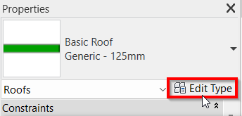
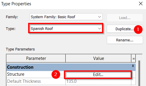
- Click Duplicate to make a new roof type. Provide a suitable name.
- Click Edit next to the Structure parameter.
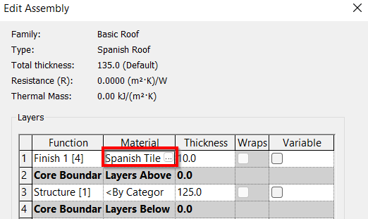
Define the roof structure, then replace the material with the Spanish tile that we defined before.
Spanish Tile Roof Result
You will see the Spanish tile roof pattern if you define everything correctly. Notice that the pattern follows the slope direction. You don’t have to arrange it manually.
Video Guide
You can refer to the following video if you have difficulties following the steps above.


Hi Edwin,
The model pattern on the roof makes sense but the pattern becomes orthogonal to the roof slope.
When seeing this in elevation, is there a way to make the pattern consistent and orthogonal to the VIEW? The model patten gets skewed in viewports since its basically sloping away from the view. See image