In this Article...
We have learned the basic of Revit families. You probably have found that creating Revit families is just a repetitive process. You create parameters, create a work plane, create a solid/void form, and create sketch. This time, we will create a door family. This door family will have solid and void forms, and you will be introduced to symbolic lines and visibility control. We will start with a very simple door in this tutorial, and add more accessories in later Revit exercise.
Creating the Door Panel
Create a new Revit family, use Metric Door.rft as your template.
This Revit template is different with what we have used before. In this template we will see a wall sample, frame/mullion, and the void for our door location. The wall is just a sample, we will not place it together with our door, when we place the door to our Revit project.
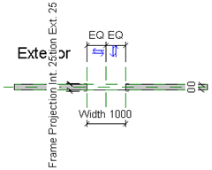
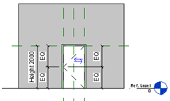
We only need to focus on creating the door panel at the provided location.
Open the exterior elevation view. Double click it in Revit project browser.

Click void from your Revit Ribbon>create tab>forms panel.

Revit will show you a drop down menu, select extrusion. Change the drawing mode to rectangle.

Draw a rectangle like below. To make sure our rectangle snapped to the work plane intersection, override the snap mode to snap intersection by pressing SI.
Hint: If you don’t snap it to the work plane intersection, your family parameters might not work!
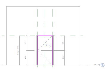
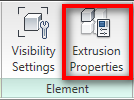
Click extrusion properties from the ribbon.
Change the extrusion end value to 50. Click OK.

We’ve just defined the door panel sketch and the panel thickness value. That would be enough for now. Click finish extrusion from the Revit ribbon.
We have done with the door panel! We will create some accessories and glass panel for this door in the next exercise. But for now, leave it like that.
Flexing the Model
Just like what we always did before, we need to test this door. Click the types button on your Revit ribbon>create tab>family properties panel.

Try to test it by changing the door height and width. The panel we created works fine. However, you can see that the dashed line is not working properly.
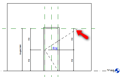
Relax, we did nothing wrong. I’m not sure you will find the same problem with imperial template. But this one is the metric template that doesn’t work properly. If you create a new family, without creating anything, you can also see this error. So it’s not our fault! Don’t worry, we will fix this. Select the dashed lines and delete it. Both of them.
Adding Symbolic Lines
We will replace the dashed lines with symbolic lines.
Revit Symbolic Lines versus Revit Model Lines
We will add lines as additional information to our door. The common information for door is the swing symbol. Revit has two types of line: symbolic and model. What is the difference between those two? When we should use it?
- Model line is a line that always visible in 2D and 3D. It’s part of your model, so you can see it in any view.
- Symbolic line is not part of the model. We can see it only in the view that we use when we draw it. And in views that parallel to it.
As we only need to show the swing symbol in each view, not in 3D, then we use symbolic lines.
The Elevation Swing
Activate symbolic line from your Revit ribbon>detail tab>detail panel.

Change the line style property to elevation swing [projection].

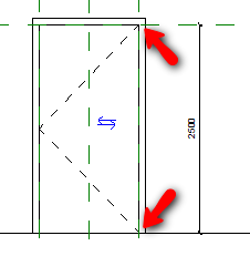
Draw the line just like what we deleted earlier. But make sure you snap to intersection at points below to avoid the same problem. Don’t worry about the mid point, just snap to a plane at that location.
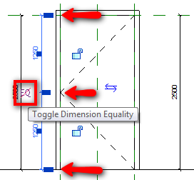
The last one. We need the lines to have the same distance from top and bottom. So add dimension like below. Snap to top ref plane, the intersection point of the dashed lines, and bottom ref plane. Place the dimension. After you place the dimension, click the EQ symbol to lock the distance to be always equal.
Hint: Press DI to activate dimension. It’s shortcut for dimension.
Test the door again. Change the door width and height. Now it should work fine.
The Plan Swing
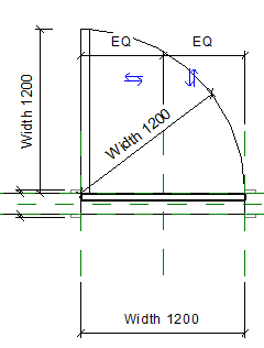
Now this is your test. Create more symbolic lines like below, and constraint them using width label.
Hiding The Door Panel
Try to load the family to a Revit project, and place the door there. If you see in the floor plan, we can see the door panel that we created with extrusion before.
Hint: You will not see the difference in family editor. You have to place it in a project to see it’s actually work fine.
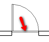
We need to show it in elevation, cut, and 3D view. But not in plan view. We need control the panel visibility. Activate modify tool, select the door panel.
Click visibility settings from Revit ribbon, contextual tab.

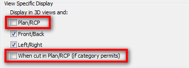
Uncheck the plan/RCP visibility and when cut in plan/RCP (if category permits). This will hide the panel in plan view and when the door cut in plan view. Click OK.
Try to load it again to your Revit project and see if it works!
We will continue with this door on later exercise, so save your file.


This helped me.
Have you ever had an issue with your visibility settings not applying to your door family? I have a door where I have told certain elements to not show up in elevation. I unchecked those two boxes. However they still show up in all views. Do you know why this might happen?
Can you send me the family to my email or provide download link? email me to edwin.prakoso@cad-notes.com.
Also some screen captures for the problem would help.
Hi, I was wondering if its possible to edit the line type of the elevation swing projection line so that it’ll be a centreline, as I would show it in AutoCAD? Thanks.
Hi Lochie,
Yes, you can change the line pattern. Read how you can do it here.
Thank.
It's so useful for me.