In this Article...
 If you are following this Revit tutorial series from beginning, you’ve already known about defining level, placing walls, placing doors/windows, define your own door type, and wall type. Now it’s time to define floors in your Revit model. Creating floors is a bit different than placing walls and doors. We have to use sketch to define this type of building component. Do you notice that I use ‘create’ word for floors and ‘place’ for wall and doors/windows?
But don’t worry, it’s not difficult!
Creating sketch
Open your previous Revit file. Open your 1st floor plan view. We will add floor on this level. Activate floor tool from your ribbon. It’s on home tab, build section.

Now you should see your plan become half toned. It means you can only see it and use it as reference for your floor sketch. Sketch? Yes, you have to define the boundary by sketching it. See your contextual ribbon tab, now it says: create floor boundary. And you will see sketching tools such as lines, rectangle, circle, etc.

The default mode for this tool is ‘pick wall’. We will get to this later, now change your draw mode to line.

Draw your boundary as below. Should be easy. Just snap to the points and use appropriate size for offset value. Make sure you are creating a closed polygon. You can’t create the extrusion if it’s not closed.
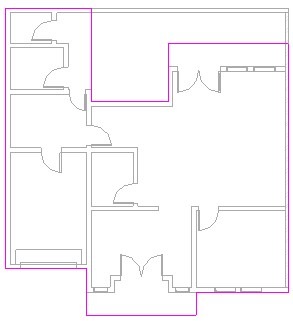
After you’ve done, click finish.
Explore your Revit model in 3D view. Now let’s move to 2nd floor plan.
Attaching walls to floors
Open your 2nd floor plan view, and activate wall tool. Now, lets’ do it a bit different. Make sure the draw mode is ‘pick wall’ ![]()
Check your option bar. Make sure the extend into wall (core) is active. This option will tell Revit to find the wall core and snap to it.
![]()
Pick these walls below. Select on the exterior side of these walls.
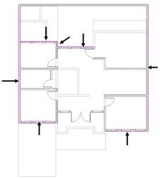
Change your drawing mode from pick walls to line. Add these lines to finish your our boundary sketch.

Now examine your sketch. This is not a closed polygon. Lines created by picking walls might extend at wall intersection. Let’s fix this. Activate trim from your ribbon.

Pick lines to trim or extend your lines. After you finish, then click finish.
You will see some dialog box asking your confirmation.

First, Revit will ask if you want your walls to attach this floor bottom? If you select yes, then every time you change the level height, your walls height will also be adjusted. We want this, so click yes.

Next, Revit will ask if you want to join geometry and cut overlapping volume. We also want this, so click yes.
After finish, let’s review the effect of selecting yes in those confirmation dialog. We will create a section view to this. Open view tab in your ribbon. Click section.

Place your section line at this position. Make sure you have your balcony and interior floor get cut.
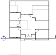
Right click at the section line, then select Go to View. Change your detail level to fine.
 |
 |
|
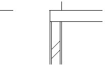
Wall is attached to floor
|
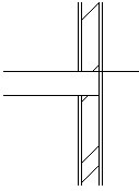
Wall core is cut
|
The image on the left is wall below the balcony. It is lowered and attached to the floor bottom. On the right, we can see the wall core is cut where it met our floor. Try to change your level height and see what will happen to these walls.
Create a void
Let’s modify our 2nd floor. We will add some space for our stair later. Open your 2nd floor plan.
Activate modify tool, then select your floor. Place your pointer above your floor edge, wait for a while until you see the tooltip shown. If you see the tooltip saying Floor Generic something, click your mouse. If you don’t press [tab] until you see it in your tooltip. Click edit boundary in your contextual tab of your ribbon bar.

You’ll be back to sketch environment.
Edit your boundary to this. This will create an opening/void for our stair.
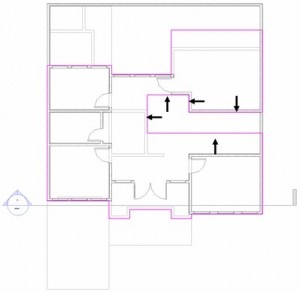
Click finish after you’ve done. Not that difficult right?
We will create another building component. See next tutorial: creating roofs in Revit model.
*You can purchase this tutorial compilation in an e-book. Find out the books in our E-Store .


If there is video to do step by step will be better