In this Article...
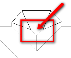
I had this question: how can I control the a complex roof in Revit? Something similar like below.
The roof doesn’t look pretty, the roof edges don’t meet at expected point.
The problem that cause this is Revit attempt to create slopes from each edges. The meeting point might not where we expect it should be. So how we can correct this shape?
There are several ways to do it:
First, You can create a mass and create roof by selecting the mass faces. Mass are quite easy to make, but using this method might be require a lot of works. If your design is quite simple, you will not want to spend to much time on your roof. I will not discuss much about this for now.
Changing slope angle and using slope arrow
To do this method, you need to select the roof and edit the roof footprint. Click edit footprint to enter the sketch mode.
Changing the slope angle
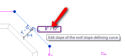
If you see the ![]() symbol, then the edge will be generated having slope. The value can be different for each edge. Select the edge and change the slope value. You can do a little math here or simply doing a trial and error until you get the expected result. It’s not fun, but it a way to do it :)
symbol, then the edge will be generated having slope. The value can be different for each edge. Select the edge and change the slope value. You can do a little math here or simply doing a trial and error until you get the expected result. It’s not fun, but it a way to do it :)
Using the Slope Arrow to control the slope direction
The trick above might work. However, you might need to control the slope direction by yourself. You can do it by using slope arrow.
Before you use slope arrow, you need to turn off define slope for the edge. Select the edge you want to control the slope direction, and turn off the define slope from option bar. If you do not turn it off, you will get an error message: The tails of slope arrows must not lie in interior of slope defining lines.
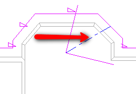
The ![]() now should disappear from that edge. Activate slope arrow. Then draw the arrow to define the slope direction. You can use height or slope value, specify the method and the constraint values from properties palette.
now should disappear from that edge. Activate slope arrow. Then draw the arrow to define the slope direction. You can use height or slope value, specify the method and the constraint values from properties palette.
Tips: For creating complex roof, it might be easier if you create separate roof then use ‘join roof’ tool to join them later.
Using Shape Editing Tools
This is the easiest way to do it. But I’m not really sure if this is a best practice. i believe this tools are not design for this purpose. You need to create the bay window roof separately. Do not give any slope to your roof edges. After you finish creating the roof, select it. You will see shape editing tools from in your ribbon, contextual tab.
This shape editing tools will not appear if you define the roof slope.
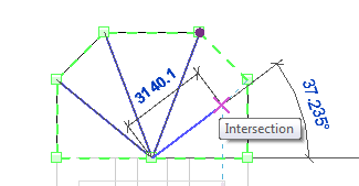
First, activate add split line and draw the lines like below. This is pretty easy to control. Easier than the previous method.
After you finish with the lines, open default 3D view. Activate modify sub elements. You can drag any point in your roof and adjust the roof shape as you want. In this sample, I only use one.
You also need to adjust the roof height to match the other roof. You can move the roof from elevation view or change the offset value.
The downside about this method is you can’t join the roof to another roof. So you will have two separate roof. I’m not sure if this will affect the model in structural or MEP analysis, but for modeling and visualization only… I guess it’s OK.
Do you have another suggestion how to do it? And what do you think about the last method, would it cause a problem later in your design process?



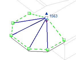


Following the last method. In elevation you can use roof by extrusion and pick lines. That will give you a clean pitched roof behind the bay section.
With courtyard
Thank you very much for this tutorial. The "The tails of slope arrows must not lie in interior of slope defining lines."-message was driving me nuts when making a simple sloped roof (shed roof).
Thanks again!
we have to fix our roof