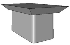
This time we will continue learning how to create Revit families. We have created a 2D profile in these posts:
- Creating Profile: Creating a simple 2D profile that can be used in many Revit families definition.
- Creating Profile Parameters: Adding parameters to add more controls for the 2D profile family. This will allow us to create several types for the same profile. Users can also define their own sizes without editing the family in family editor. They can simply change it while working on a Revit project.
If you are new to creating Revit families, I suggest you to read them first. Now, we are going to create a 3D Revit family. Let’s start with something simple. The objective in this post is you can create 3D objects using Revit family editor. No, no parameters yet.
I know many of you already familiar with extrude, blend, revolve, etc. But if you are not familiar with 3D modeling yet, don’t worry. We are going to use simple objects here.
Creating a New Family
Create a new family. Select the ‘Metric Furniture.rft’ template.
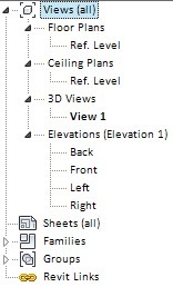
It’s a little different with 2D profile. See the Revit project browser. Here you can see the tree showing 3D views. Not only plan view.
Creating a Table Bottom
Open view: Floor plans>Ref. Level. Double click the view from your Revit project browser. We will see two dashed lines crossed on the center of the screen. The intersection point is the insertion point of your furniture. This is similar to insertion point of blocks in AutoCAD.
Activate extrusion in create tab, forms panel. Click the solid button, and click the extrusion from drop down menu.
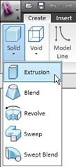
This will bring you to the sketch mode. We need to create a closed profile before create an extrusion. Create a rectangle like this. Don’t worry about the size. We will adjust it later.
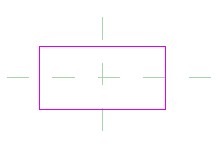
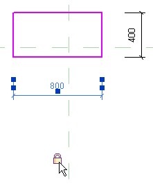
Create a dimension that define the table bottom size. Change them to 800x400mm. Press [esc] several times until modify tool is active. Click to select the dimension. You should see the lock symbol when the dimension selected. Click it to lock the distance. Do it for both dimension.
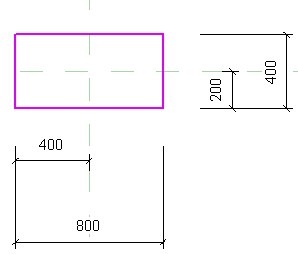
Now add dimension from the left side to vertical axis. Change the distance to 400mm. Do the same for the horizontal lines. I found a hard time defining the distance with equal dimension. I can use it in parameters, but not if only use dimension. So I decide to use dimension like this. If you know how to get it works, please share with us.
We are going to use equal dimension when we start using parameters.
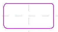
Optional: You can try using more fancy design if you wanted to. I created this profile with filleted edges.
Click extrusion properties, it’s on your ribbon tab, element panel. Change the ‘extrusion end’ value in constraint group. Change it to 400.

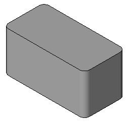
Click finish extrusion. Check the table bottom in 3D view.
Let’s create the table top.
Creating a Table Top
Creating Reference Plane
Before we continue creating another solid object, we need to define a reference plane. We want to create the table top, right above the table bottom. We need to move our working plane from the floor level above it.
Open an elevation view, any view. Click reference plane>draw reference plane.
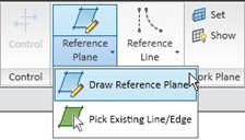
Snap to the top of our extrusion before. Draw the plane.

On your ribbon, work plane panel, click ‘set’ button. In the opened dialog box, select pick a plane.
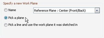
Click OK. Select the reference plane you just created before.
Revit will open another dialog box, asking where you want to work. We have to work with a working plane parallel to our screen.
Select floor plan: ref. level, then click open view.
Creating a Blend
Creating blend is similar to creating extrusion. But when we create extrusion we only define one profile, blend is using two profiles. Activate blend from your ribbon, form panel. Click the small arrow below solid button.
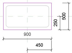
Click blend properties from your ribbon. Change the second end value to 100.

Now, we need to define the top profile. Click edit top from ribbon. Create another profile, slightly offset from the previous profile.
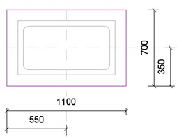
Click finish blend.
Check your table in 3D view.

Next, ne are going to create more advanced 3D Revit family by adding parameters.


Hi Edwin,
Do you have any tutorial for adaptive massing?
Hi Ram,
Not yet. I'm currently working on a conceptual design series. Adaptive massing is in the posts. If you need it now, you may want to take a look at Revit Clinic. They have a video about the adaptive capabilities a couple of weeks ago.
Thank you for your reply.
Do you have an alternative email add where I can attach the image? We have a sample family of table (which we got from other source). The original width of it is 1200mm with 4 legs, as the width lengthens, the legs automatically add, spaced equally, depending on the length of the table. When you insert the component to a project, you point on the start and end of the table, which is the width.
We need to do the same thing for cabinet/ counter/ closet but we don't know how to do it systematically. I hope you understand my explanation. Thank you so much!
I sent an email to you, simply reply and attach the file there.
I'm sorry I don't open my email address for public to prevent spammer bots to find my email :)
Hello! May I know if you have a tutorial in making a cabinet/ counter/ closet family using 'point to point' method. I have no idea on how to create it. Could you help me with this one. Thank you so much! I'll wait for your reply.
Hi Vizel,
I'm not sure what you mean by 'point to point' method. Could you give me a sample/sketch what you want to achieve?