Another great tips from Hai Le (@ThatCADguy).
This double click feature allows the user to space an individual dimension (accordingly to the MMI 3/8” spacing standards) by double clicking a neighboring dimension. The following steps will guide you through a series of instructions to create this feature.
By default, DIMSPACE command allows you to input the distance manually or choose auto. Auto distance will give you distance 2x of text height. Now we will see how you can change it to 3/8”. The are various ways to place this custom command, like in toolbar, ribbon panel, or context menu (right click). In this tip, we will use it in double click action.
1) Execute the Customize User Interface dialog box by typing ‘CUI’ into the command line.
2) Create a new command. If you are not familiar with creating new command in CUI, refer to this article: Exploring AutoCAD CUI: Creating a command.
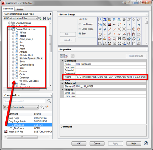
3) Fill out new command Properties. (See image below)
- Name: HTL_DimSpace
- Description: This command will automatically space a dimension at 3/8” times the scale factor from a selected dimension. (Optional)
- Command Display Name:
- Macro: ^C^C_dimspace;\(SETQ DS (GETVAR “DIMSCALE”)G:TS (* 0.375 DS));

4) Find the Double Click Actions tab under Customization in All Files and drag your new command from the Command List into the option labeled ‘Dimension.’
Now try to double click a dimension then click another dimension as base. You will see the dimension space is adjusted to 3/8” (or 0.375).
More readings
If you want to learn more about CUI: 5 articles to learn about AutoCAD CUI.
If you want to know more about macro: How to automate AutoCAD with command macro.
Thank you to Hai Le for the great tip!


Hi,
Great idea but doesn’t work in Autocad 2016 LT
The result I get is the dimensions in exactly the same line i.e. no spacing.
I checked my “dimscale” variable value and this is 0.00 so I tried “dimtxt” variable instead
e.g.
^C^C_dimspace;\(SETQ DS (GETVAR “DIMTXT”)G:TS (* 0.375 DS));
But got same result. i.e no spacing.
Also buy using this command I can no longer edit dim text by double clicking what do you do to edit dim text when overriding it with Dimspace?
Hi,
great command but I can’t get it to work. The results I get are the dimensions end up exactly inline with each other. I checked my “dimscale” variable value and this is “0.000” so I tried using “DIMTXT” variable instead
e.g.
^C^C_dimspace;\(SETQ DS (GETVAR “DIMTXT”)G:TS (* 0.375 DS));
I am using AutoCAD 2016 LT.
also is their away to keep dim text edit as a double click function also, if not what do you do for this command?
When i made this macro i received an error – :error: bad argument type:( or stringp):nil. why am i getting this error. I am using ver.2014
Does not work for Autocad 2015. It will give me a different spacing
Hello,
sorry I m to stupid :-( , but my Dimension doesn’ t
react this way by Double Click.
As I understood you, there is a standard behabvior in AutoCAD 2016:
When making a linear DIm
I set the 3 rd Pick to the neighbour Dimension to get the right Distance for my own Dimension.
I don t get a right distance. This has nothing to do with your nice Lisp pushed macro. I mean the standard behavior.
You have an idea ?
Andreas
i would like to set this up for use in metric. i like to off set my dimensions 10x the scale i’m using (eg: 1:50mm i off set 500mm).Please can you shed some light on how to set this up. Thank you in advance.
Donovan,
Simple macro like this can’t work like you want. You need to create several macros, one for each scale.
thats fine, i only use a few scales so i don’t mind doing that, how would i go about creating these macro’s ?
I’m getting an error when using as toolbar button
; error: bad argument type: (or stringp symbolp): nil
How would this look like when using millimeters?
Just change 0.375 to 10 or is there more to it?
I can’t test this because of error
Thanks
Hi Coen,
Did you type the macro or copy and paste it from this webpage? It could be because the code is not translated correctly.
Do you use AutoCAD or AutoCAD LT? What version?
I use autocad full version 2011, 2013, and 2014
I copy paste the code from the website and tried typing it.
I tried this in all three versions with the same result