In this Article...
This is the first of a simple MicroStation 3D modeling tutorial series, from basic modeling tool, rendering, to creating animation. To follow the exercises, you need to be be familiar drawing in MicroStation 2D. If you are not familiar with MicroStation 2D yet, you can try to read this MicroStation tutorial series first.
Creating and Preparing 3D Design File
Start your MicroStation. You may want to create a new project for this MicroStation 3D tutorial, so the files are separated with your other projects. Create a new file.
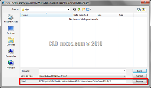
Before you click save, make sure you are using seed3d.dgn. If you are not using it, click browse and select the MicroStation 3D template.
Open the file.
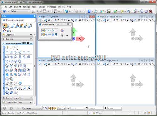
So what are the differences between 2D dgn and 3D dgn? In 3D modeling we have 3 axis: X, Y, and Z. You will see more view tools too. By default MicroStation 3D seed will open 4 views. Examine the view tools.
There are also many tools that you don’t have in 2D design can you see here. We will learn about it later.
Changing the Working Unit
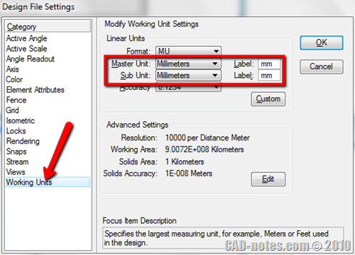
I usually use metric, so it’s the unit we are going to use in this tutorial. Open MicroStation menu, go to settings>design file. Choose working unit category. Change the master unit to millimeters.
Click OK to close the dialog. Click [ctrl] + F to save settings.
Creating Table Legs
Let us start to create our windows panel. There are many 3D tools that we can use. However, the process is usually very simple but require repetitions. Most CAD applications use the same workflow.
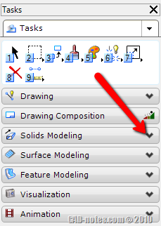
Where are the 3D tools? In MicroStation tasks bar, find solids modeling tools. Click down arrow to expand it.
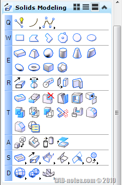
Now you will see several tools groups that you can use to create 3D solids. Don’t be intimidated to see so many tools available here. After you start using them, you will see that they are easy to use.
Using Primitive Solids
Primitive solids are solid forms that are ready to use. You can simply place primitive solids from MicroStation task. However, the solid forms are limited. You need to use other tools to create more complex forms. See what can you create with primitive solids.

Using Slab Solid Tool
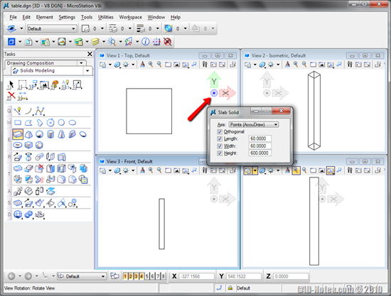
Let us try with slab solid. Activate the tool. The slab solid tool settings are now showing options related to creating slab solid. You can fill the slab solid size here, or using AccuDraw. See this MicroStation 2D tutorial how they are related. This time, fill all the values like below.
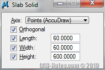
Now click on empty space in top view. The interesting thing when working with MicroStation in 3D is each view has it’s own axis. When you move your pointer inside a view, the axis color will turn to green and red. It means, MicroStation will use that axis.
Now move your pointer to the right to define length, click data point. Move your pointer up, click data point.
To define the height, you need to move to other view. Use front view, move your pointer above then click data point. You created a slab!
Using Construct Array Tool
You can also use manipulate tools in 3D, just like you use them in 2D. Now let us use a manipulate tool: construct array. Select the table leg in top view, then change the tool settings value as below.
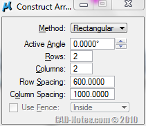
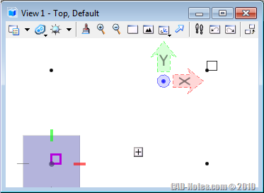
Before you continue, let us see the array preview in top view. This looks OK. But before you accept the array, try to move your pointer to front view.
Now you will see the preview updated instantly. MicroStation will use this view axis and change the objects’ position.
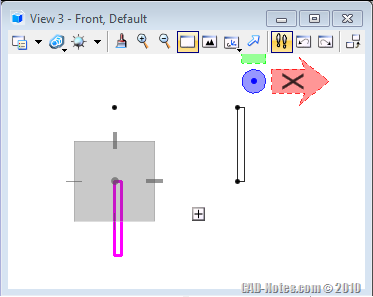
Move back to top view and accept the array.
Changing Display Mode
Before we continue, let us change the display mode on isometric view. Find display mode button, click and hold it until you see the predefined display mode. Change to hidden line or illustration.
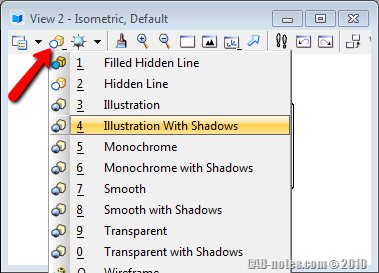
Completing Table’s Leg
Now activate place slab tool again. This time we are going to create another slab tool. When you already have many objects in your design file, it is easier to pick the points from isometric view. So move your pointer above the point shown below.
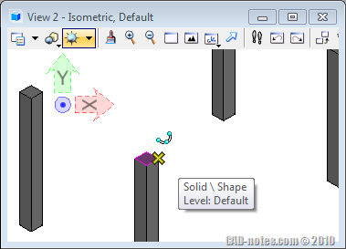
We don’t want to start the slab at that point, but we want to offset it below. If you are already familiar with set origin tool, yes we are going to use it. See this set origin animation if you are not familiar with it yet.
Now when you see the yellow cross, click temporary snap. Click both of your left and right mouse button at once. This will move focus to AccuDraw. Press O to activate set origin.
Now move to front view. Move your pointer below the reference point, type 50 then press [enter]. Click data point. This should define the slab first point 50mm below the reference point.
Now use top view or isometric view. Move your pointer above point on the other table leg. Don’t click it yet! Review how the slab would be if you click it now in front view. Do we need to set origin again?
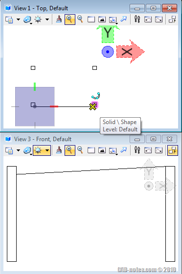
No, you don’t have to. Move your pointer away until you don’t see the yellow cross in your pointer. Press Z. This will lock Z to 0 value, and try to snap to that point again. If it does looks right, click data point. Complete the slab.
Now can you finish the rest of the table? See video below as your guide!
We use only one basic tool to create this simple table. In this tutorial, I would like to show you how you can work with view’s axis, using manipulate tools, and other tools you usually use in 2D drawings. We will do more exercises later.


Hi, for some reason i cannot find construct array tool. Is there an alternative or am i missing it?
Thank you. There are not enough Microstation resources as it pertains to architecture and interior design out there. Do you have any more?
Hi Makeda,
I’m glad that it helps. Unfortunately I don’t have access to MicroStation anymore.
So I can’t post more about it.