In this Article...
As we know, in Inventor we can simulate welding process an Assembly model. Those commands to simulate welding process can be activated when we select “Convert to Weldment” ![]() in Environment tab on “Convert” panel. There are disadvantages and advantages of doing this.
in Environment tab on “Convert” panel. There are disadvantages and advantages of doing this.
The disadvantages are:
1. When you activate Weldment Commands or work in Weldment Assembly Model ![]() , you can’t convert back to regular Assembly model
, you can’t convert back to regular Assembly model ![]() .
.
When you activate it, you should see this warning:

2. You won’t be able to do Dynamic Simulation, because all features related to Dynamic Simulation will be inactive.
The advantages are:
1. We can simulate various construction of welding with various filler material in different weldings. As we know that in usual Assembly model we usually have problem when we want to show material types in worksheet part list.
But if we convert it to Weldment Assembly we will be able to show material types in worksheet part list. Compatible with type of filler material we use.
Look at picture below!

2. We can make drawing with four process level Assembly.

As we know that in fabrication process that need high precision, there’s machining process for finishing step which usually called Finish Machining. Before it reach finish machining step, raw material should pass preparation process or pre-machining and welding process.
Look at picture below.

3. With levels in Weldment Assembly, we can estimate need of raw material for every part before Finish Machining process.
What I will show you this time is how to make a Weldment Assembly that need good precision, without avoiding preparation process and raw material needed. I have an example for this session. The example is a Top Cover with Flange. This part consist of Flange and Dished and need a good precision because the part will assembled to Lower Flange with O-ring and Bolted connection. See image below for the part.

Follow these steps to make the part.
A. Make Preparation Part
Before you assemble parts that will be processed for finish machining, you have to know first how much clearance that usually applied into parts before finish machining process in your workshop. Usually for economical reason and streamlined using of raw material, every part that will through machining process will exceeded > 5mm each side. Look at picture below.

With provision above, make preparation model for Flange as follows:
a.1 Click “New” ![]() on “Get Started” tab and select “Metric” templates on left column and then select “Sheet Metal (mm).ipt”, then click “Create” button on lower section of “Create New File” dialog box. Blank window will be opened and we are ready for creating new part.
on “Get Started” tab and select “Metric” templates on left column and then select “Sheet Metal (mm).ipt”, then click “Create” button on lower section of “Create New File” dialog box. Blank window will be opened and we are ready for creating new part.
a.2 Click “Create 2D sketch” ![]() then select plane where we will locate the sketch. For example, select “YZ plane” on model browser.
then select plane where we will locate the sketch. For example, select “YZ plane” on model browser.
a.3 Select “Project Geometry” ![]() on “Draw” panel in “Sketch” tab. Then select “Centerline” in “Format” panel. Select “Y axis” on model browser. Right click and select “ok”. Continue same procedure to set horizontal reference, for example Z axis.
on “Draw” panel in “Sketch” tab. Then select “Centerline” in “Format” panel. Select “Y axis” on model browser. Right click and select “ok”. Continue same procedure to set horizontal reference, for example Z axis.
a.4 Make sketch with dimensions that will be attained in finish machining process (Finish Machining Dimension). Don’t forget to make this sketch in Construction Sketch form.
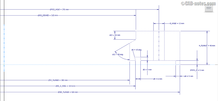
a.5 Click “Finish Sketch” ![]() command in “Exit” panel. Then make second sketch with same plane and reference as previous step. In this sketch, make preparation sketch with clearance dimension 5mm each side. Use “Project Geometry” feature
command in “Exit” panel. Then make second sketch with same plane and reference as previous step. In this sketch, make preparation sketch with clearance dimension 5mm each side. Use “Project Geometry” feature ![]() to project Finish Machining Sketch that created before. Click “Finish Sketch” command in “Exit” panel.
to project Finish Machining Sketch that created before. Click “Finish Sketch” command in “Exit” panel.
The result sketch will like picture below.
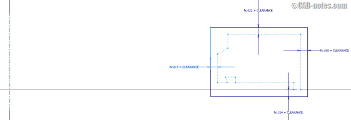
a6. Click “Revolve” on “Create” panel in “3D model” tab. Revolve dialog box will show, then select sketch available as profile and Y axis as revolve axis.

a7. Select “Parameters” ![]() command in Parameter panel on Manage tab. Then parameter dialog box will show up like picture below :
command in Parameter panel on Manage tab. Then parameter dialog box will show up like picture below :

On “Model Parameter” section, in “Parameter Name” column, names you’ve created will be shown. After that, check on “Export Parameter” column. Click “Done” to save the changes.
a8. Expand “Parameters” panel on “Manage” tab then select “Export to XML”. Export to XML dialog box will be opened. Save that file with name “Flange – Parameters”.
a9. Save the file with name “ Flange”.
Make preparation model for Dished by follow these steps :
a10. Click “New” ![]() on “Get Started” tab and select “Metric” templates on left column and then select “Sheet Metal (mm).ipt”, then click “Create” button on lower section of “Create New File” dialog box. Blank window will be opened and we are ready for creating new part.
on “Get Started” tab and select “Metric” templates on left column and then select “Sheet Metal (mm).ipt”, then click “Create” button on lower section of “Create New File” dialog box. Blank window will be opened and we are ready for creating new part.
a11. Click “Create 2D sketch” ![]() then select plane where we will locate the sketch. For example, select “YZ plane” on model browser.
then select plane where we will locate the sketch. For example, select “YZ plane” on model browser.
a12. Select “Project Geometry” ![]() on “Draw” panel in “Sketch” tab. Then select “Centerline” in “Format” panel. Select “Y axis” on model browser. Right click and select “ok”. Continue same procedure to set horizontal reference, for example Z axis. Then make sketch like picture below.
on “Draw” panel in “Sketch” tab. Then select “Centerline” in “Format” panel. Select “Y axis” on model browser. Right click and select “ok”. Continue same procedure to set horizontal reference, for example Z axis. Then make sketch like picture below.
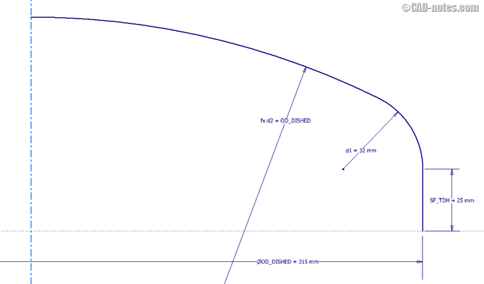
a13. Click “Revolve” on “Create” panel in “3D model” tab. Revolve dialog box will show, then select sketch available as profile and Y axis as revolve axis. Change “Output” to “Surface” and “Full” in “Extents” dropdown menu. Click “OK” to end revolve command.

a14. Click “Thicken/Offset” command in “Surface” panel on “3D model” tab, then “Thicken/Offset” dialog box will show. Select all the surfaces and input 7.5 mm in the “Distance” with direction as picture. Click “OK” to end command.

a15. Save the file with name “ Dished”.
B. Preparation Part in Assembly Weldment
b1. Click “New” on Application Option, then select “Metric” templates and select “Standard(mm).iam”. After that, click “create” button to create an assembly.
b2. Select “Place” on “Component” panel on Assemble tab, then “Place Component” dialog box will open. Select Flange for first part that will be assembled, then select “Open” on lower area of “Place Component” dialog box.
b3. Expand “Origin” and “Folded Model” of Flange part in browser like picture below.

b4. Click “Constraint” on “Relationship” panel in “Assemble” tab, then “Place Component” dialog box will open. Select “Mate” ![]() in “Type” column and “Flush”
in “Type” column and “Flush” ![]() in “Solution” column. After that, select origin plane on both Flange and Assembly model. If you select “YZ” plane on Master Skeleton, you should also select “YZ” plane on Assembly model.
in “Solution” column. After that, select origin plane on both Flange and Assembly model. If you select “YZ” plane on Master Skeleton, you should also select “YZ” plane on Assembly model.
b5. Continue constraint allocation on three planes to make it fully constrained.
b6. Click “Convert to Weldment” on “Convert” panel in “Environments” tab, and click “Yes” button to accept the attention. So Convert to Weldment dialog box will shown.

b7. Select “ISO” for Standard, select “Stainless Steel” in Weld Bead Material drop down menu and make default for another setting. Click “OK” to save changes.
b8. Now, the Assembly Model ![]() will change become Weldment Assembly Model
will change become Weldment Assembly Model ![]() .
.
b9. Save the file with name “Top Cover with Flange”.
Manage the parameters before you get in to Preparation stage, it’s used to decrease error when we change Preparation and Finish Machining dimensions. Follow these steps.
b10. Click “Import from XML” in “Manage” panel on “Manage” tab. Open Flange – Parameters have created.
b11. Show “iLogic” browser by clicking “iLogic Browser” panel in “Manage” tab .
b12. Click “Add Rule” on the same panel and tab, and name it Top Cover with Flange – Rules. Then “Edit Rule” dialog box will open.
Fill blank window of “Edit Rule” dialog box with codes like picture below.
b13. On “Model” tab expand Flange:1 then click on “Model Parameter”. Parameters in Master Skeleton will be shown in right column. Double click on parameter name in Parameter column to open iLogic editor.

Those codes connect the Assembly’s Parameters with Part’s Parameter.

b14. After that, do same thing on parameter assembly by placing it in the same name. Click “Ok” in “Edit Rule” dialog box.
Inventor will synchronize parameters between Assembly and Parts. So if we change dimension in Assembly, dimension in Parts will also changed.
b15. Click at “Preparation” on “Process” panel in “Weld” tab to activate the Preparation stage.
b16. Click “2D Sketch” on “Sketch” panel in “Weld” tab. Select “YZ Plane” in model browser as reference plane. Right click in window and select “Slice Graphics” to make sketch easy to seen.
b17. Select “Project Geometry” ![]() on “Draw” panel in “Sketch” tab. Then select “Centerline” in “Format” panel. Select “Y axis” on model browser. Right click and select “ok”. Continue same procedure to set horizontal reference, for example Z axis.
on “Draw” panel in “Sketch” tab. Then select “Centerline” in “Format” panel. Select “Y axis” on model browser. Right click and select “ok”. Continue same procedure to set horizontal reference, for example Z axis.
b18. Create sketch to make groove for placing Dished before welding process.
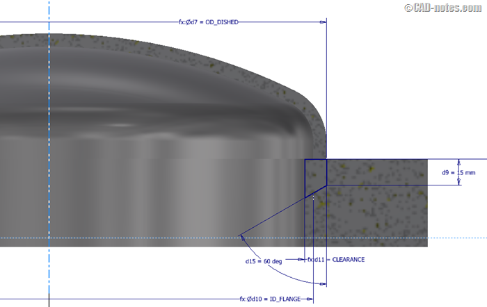
Click “Finish Sketch” command in “Exit” panel.
b19. Click “Revolve” on “Preparation and Machining” panel in “Weld” tab. Select sketch that have created as “Profile” and “Y Axis” in model browser as “Axis”. And make default for other setting then click “OK” to end command.

b20. Click “Chamfer” on “Preparation and Machining” panel in “Weld” tab. Select “Distance” for type of chamfer. Select top inner edge of Flange as “Edges”, and enter value as picture below. Click “Apply” to create a chamfer.

b21. Click “Return” on “Return” panel in “Weld” tab to end Preparation stage.
b22. Select “Place” on “Component” panel on “Assemble” tab, then “Place Component” dialog box will open. Select Dished then click “Open” to place the Dished.
b23. Click “Constrain” on “Relationships” panel in “Assemble”. Select “Insert” for the “Type” and “Opposed” for “Solution”. For first “Selections” select Dished’s edge and second “Selection” select groove’s edge like picture below. Click “Apply” to apply this constrain. For second constrain, select “Mate” for the “Type” and “Mate” for “Solution”. For first “Selections” , select “YZ Plane” on origin of Dished and second “Selection” select “YZ Plane on origin of Flange and then click “Apply” to apply this constrain.
b24. Select “Half Section View” ![]() and select “YZ Plane” in Assembly Model to see sectional area of Assembly.
and select “YZ Plane” in Assembly Model to see sectional area of Assembly.
b25. Right click at “Preparation” in Model Browser then select “Edit” to activate the Preparation stage.
b26. Click “Chamfer” on “Preparation and Machining” panel in “Weld” tab. Select “Distance and Angle” ![]() for type of chamfer. Select bottom face of Dished as “Face” and edge of Dished as “Edges”, and enter value as picture below.
for type of chamfer. Select bottom face of Dished as “Face” and edge of Dished as “Edges”, and enter value as picture below.

b27. Click “Return” on “Return” panel in “Weld” tab to end Preparation stage.
C. Welding Process Simulation
c1. Click at “Welds” on “Process” panel in “Weld” tab to activate the Welding stage.
c2. Select “Groove” on “Weld” panel in “Weld” tab. Select bottom groove face of Flange as “Face Set 1” and check “Full Face Weld”. Select bottom face of Dished as “Face Set 2” and check “Full Face Weld”. Click “Apply” to create a welding simulation. See picture below.
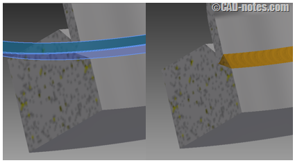
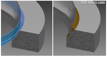
c3. Select “Groove” on “Weld” panel in “Weld” tab. Select chamfer face of Flange as “Face Set 1”, then select outer straight face of Dished as “Face Set 2”. Check “Radial Fill” as “Fill Direction”. Make default for other setting. Click “Apply” to create a welding simulation. See picture below.
c4. Click “Return” on “Return” panel in “Weld” tab to end Welding stage.
D. Finish Machining in Assembly Weldment
d1. Click at “Machining” on “Process” panel in “Weld” tab to activate the Machining stage.
d2. Click “2D Sketch” on “Sketch” panel in “Weld” tab. Select “YZ Plane” in model browser as reference plane.
d3. Select “Project Geometry” on “Draw” panel in “Sketch” tab. Then select “Centerline” in “Format” panel. Select “Y axis” on model browser. Right click and select “ok”. Continue same procedure to set horizontal reference, for example Z axis.
d4. Create closed sketch with Finish Machining dimension that is want to be attained (as created in Flange part). If you need reference, expand “Folded Model” on Flange:1 in Model Browser, then click “Sketch1”. Then Finish Machining will show. Follow that sketch to ease this sketch creation. Follow picture below.
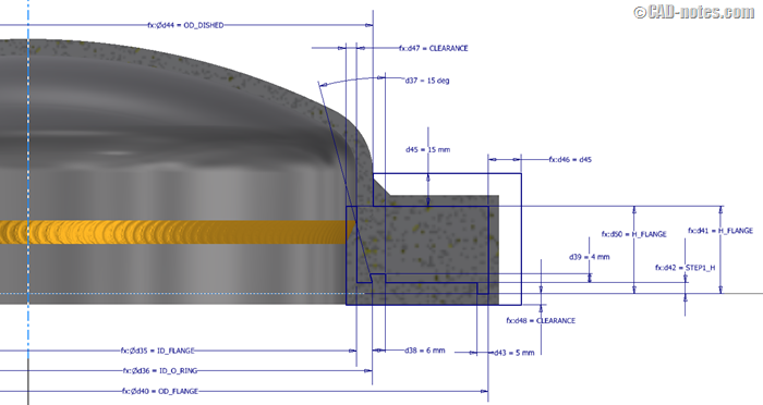
Sketch with Finish Machining dimension is area that will be maintained. Whereas outer sketch is area that will be eliminated as scrap.
d5. Click “Revolve” on “Preparation and Machining” panel in “Weld” tab. Select sketch that have created as “Profile” and “Y Axis” in model browser as “Axis”. And make default for other setting, then click “OK” to end command.
d6. Click “2D Sketch” on “Sketch” panel in “Weld” tab. Select “XZ Plane” in model browser as reference plane.
d7. Select “Project Geometry” on “Draw” panel in “Sketch” tab. Then select “Center Point” in model browser. Draw a circle in format Construction Line and then give dimension PCD_HOLE. After that, draw a point everywhere at the circle, and give a “Vertical Constrain” with “Center Point”. Click “Finish Sketch” command in “Exit” panel.
d8. Click “Hole” on “Preparation and Machining” panel in “Weld” tab. Select “From Sketch” on “Placement” dropdown menu. Select “Trough All” for “Termination” and give D_HOLE as dimension of hole. Make default for other setting. Click “OK” to end command.

d9. Select “Circular” on “Pattern” panel in “Weld” tab. After that, select “Hole 1” in Model Browser as “Features” and then click arrow beside “Rotation Axis” and select “Y Axis” origin of Assembly. Enter the value as picture below.

Click “OK” to create pattern holes.
d10. Click “Return” on “Return” panel in “Weld” tab to end Machining stage.
d11. Select “End Section View” and see the result.

d12. Show “iLogic” browser by clicking “iLogic Browser” panel in “Manage” tab . Right click at “Top Cover with Flange – Rules” and select “Edit Rule”. Add this rule below rule that has created before.
![]()
This rule used for controlling Outside Diameter of Dished dimension so it keeps matching with the flange.
E. Testing iLogic Rules
e1. Save file “Top Cover with Flange” as new file with name “Top Cover Modified”.
e2. Open file “Top Cover with Flange”. Select “Parameters” command in “Parameter” panel on “Manage” tab. Change ID_FLANGE to 600mm and click “DONE” to save the changes. See the result!

e3. Change ID_FLANGE to 300mm again and click “DONE” to save the change.
e4. Open file “Top Cover Modified”. Show “iLogic” browser by clicking “iLogic Browser” panel in “Manage” tab . Right click at “Top Cover with Flange – Rules” and select “Delete”. Change ID_FLANGE to 600mm and click “DONE” to save the change. See the result!

Analysis :
With the iLogic rule that is used to control the dimensions of the assembled parts, the possibility of error will be less.
e5. Change ID_FLANGE to 300mm again and click “DONE” to save the change.
F. Make View Representations
Before we create worksheet drawing, it’s better for us to make View Representations first. It’s useful to ease us choosing certain parts of model we created appropriately without ruin relation or constraint between one and another part.
f1. Expand “Representations” in Model Browser. Expand “View”, then it will show 2 view representations and “Default” is currently active view representations ![]() .
.
f2. Right click at “View” ![]() and select “New”. Then “View 1” will be created and rename it with “Flange View”.
and select “New”. Then “View 1” will be created and rename it with “Flange View”.
f3. Right click at “Flange:1” in Model Browser and “Isolate”. So that only Flange will shown in window.
f4. Do same step to create “Dished View”.
G. Drawing for Manufacturing (Fabrication)
g1. Click “New” on Application Option, then select “Metric” templates and select “ISO.dwg”. After that, click “create” button to create a drawing.
g2. Click “Base” on “Create panel” in “Place Views” tab. So, Drawing View dialog box will show. In “Component” tab click “Open Existing File” beside “File” dropdown menu and select Top Cover with Flange.iam.
g3. Select “Flange View” in View column, then select “Top” for Orientation and enter “1:4” for Scale. Make default for other setting in “Component” tab.

g4. In “Model State” tab, select “Preparation” mode on “Weldment” column and select “Flange:1” to show preparation stage of Flange in the drawing. Make default for other setting and click “OK” to create drawing.

g5. Right click on window and select “OK” end command.
g6. Create a section and give dimensions like picture below.

g7. Do same step to create a drawing for preparation stage of Dished.
g8. Click “Base” on “Create panel” in “Place Views” tab. So, Drawing View dialog box will show. In “Component” tab click “Open Existing File” beside “File” dropdown menu and select Top Cover with Flange.iam.
g9. Select “Default” in View column, then select “Top” for Orientation and enter “1:4” for Scale. Make default for other setting in “Component” tab.
g10. In “Model State” tab, select “Welds” mode on “Weldment” column. Make default for other setting and click “OK” to create drawing.
g11. Create a section, give dimensions and welding symbols like picture below.

g12. Click “Base” on “Create panel” in “Place Views” tab. So, Drawing View dialog box will show. In “Component” tab click “Open Existing File” beside “File” dropdown menu and select Top Cover with Flange.iam.
g13. Select “Default” in View column, then select “Top” for Orientation and enter “1:4” for Scale. Make default for other setting in “Component” tab.
g14. In “Model State” tab, select “Machining” mode on “Weldment” column. Make default for other setting and click “OK” to create drawing.
g15. Create a section, detail, and give dimensions like picture below.

g16. If it needed, give explanation for each execution stage to clarify drawing.
g17. Save file with name Top Cover with Flange – Dwg
Please download complete drawing in following link: http://a360.co/1ilfBoI
Now, you have a complete drawing to fabrication process only use one Weldment Assembly Model.
The steps above can be applied to make parts with large dimension but no need to be done by casting or foundry process, so it saving use of material and manufacturing cost.
Drawing steps above has applied by writer in daily activity as Mechanical Drafter in fabrication drawing process. Hopely this writing will be useful for you. Have a try.


