
Parametric feature is very useful if you have similar object with slightly different geometry or size. In manufacturing, if you have nuts and bolts that looks the same, but have different sizes, parametric features is perfect for this purpose. This kind of remind us about dynamic block, isn’t it? Dynamic block has the same purpose, but has limitation. I can’t figure yet how we can use it in AEC industry, except for reusable contents.
So this time, we are going to create a column with dynamic block. This is similar with the column we created in dynamic block tutorial. But we are not using the parameter and action. We are going to use geometric and dimension constraint. We will see how we can get different dynamic block behavior.
For a start, let’s create two rectangles like this.

I made a 200x200mm rectangle and offset it 20mm to outside. The 200x200mm is the column, and 20mm is the column finishing layer. Make it as a block, and use the center of the rectangle as insert point. Same like we did before.
As usual, to add ‘dynamic’ behavior to the block, we need to open it in block editor. Let’s forget the block authoring palette for a while. We will focus on the contextual tab: block editor.

Let’s activate the dimensional constraint. use linear dimension, and snap to the rectangle end points. Change the constraint name immediately to h and w like below.

Now we will tell AutoCAD that we want the finish thickness is 20mm. Let’s add one more constraint, name it finish.

Here is the deal. We have four rectangular sides that need to define the offset distance. Add them all and when AutoCAD ask you for the value, type ‘=finish’. It means we are going to use the same value as the previous constraint.

And when AutoCAD ask you the number of grips, enter 0. We don’t need it since we refer to ‘finish’ constraint. Here is the finished dimension constraint placement.

We haven’t finished yet. But let’s test it before we continue. Click parameter manager button on your ribbon.

As you can see, the result can be unpredictable! Why? We haven’t tell AutoCAD the objects relations to each other. We need to add geometric constraint.

Undo until you see the rectangle back. We will add geometric constraint to these rectangle. Instead of adding them one by one, let’s activate Auto Constraint. Press S then [enter] to change the settings. Deactivate all, except perpendicular. We want or rectangle sides to be perpendicular to each other.

Click OK then select them all. Add one horizontal constraint to any horizontal edges. You can left the whole constraint on actually. Not just the perpendicular. I just want you to know the option exist :)
Try to change the parameters again. We still have a problem: the insertion point is shifted.

The last thing, we need to define a fixed point as the center of the column.
Let’s create a point at #0,0. You can activate point by typing POINT then [enter]. Then type #0,0 [enter]. If you can’t see the point, type DDPTYPE [enter] to change the point appearance.
Lock it at its position using fix constraint.

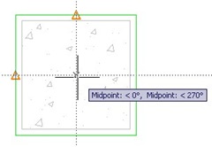
Now add dimensions from the point to the rectangle edges. Use h/2 and w/2 as the value. This will make sure our column center won’t shifted.

Let’s try again. Does it work?
We will explore this column again next time.


I have created a dynamic block with dimensions that works perfectly in a layout but when I take that block and the other items to make one large block out of it all, the dynamic blocks dimensions span only to the longest dimension the block had created in it, the dimension of the shorter dynamic blocks dimensions created within that block do not stay with it, it continues to only dimension the lonest span any suggestions? Perhaps it is just as easy as an option I did not select in creating the block?
Are you creating a nested block? A block that consists multiple blocks?
Dynamic block won’t work correctly if you do that. But if you can upload the block and share it here, I’ll take a look.
You can upload it to DropBox or OneDrive and share the link here.
Hi,
Hope someone out there can help me. I’m trying to create a block (a bolt/nut/washer assembly) that can be dynamically stretched (Grip & Bolt Length), but can also be selectable by size. It also has some visibility states (Side view/ End view/ Bolt only/ Normal Nut/ Locking nut….and so on), but this is incidental to my problem so ignore that for now.
The block I’ve made is now fully functional but for one problem. The single dynamic grip glyph associated with my GRIP Linear Parameter (stretch action) will not stay in place when the size of bolt is selected from the block properties table (to anything other than the default size). The grip stays where it should (inside midpoint of washer) when the grip is adjusted while still on the default inserted size of bolt, so it is included in the stretch operation. I tried to dimensionally constrain the grip glyph to the washer midpoint, but this appears not to be a valid operation, unless I’m missing something.
Unless I can get the Block Properties Table/Dimensional constraints to co-exist with the Dynamic Linear Parameters/Actions I’ll just have to stick with having a separate block for each available block size.
Has anyone come across anything similar and found a proper solution or even a workaround?
Does AutoCAD LT 2015 have the dynamic constraint feature, only my ribbon looks nothing like yours…
All I can see in the Parametric -> Dimensional tab is ‘Show/Hide’ ‘Show All’ & ‘Hide All’
can autocad walls be used in a dynamic block
Yes. See this dynamic block tutorial.
I'd use parametrics for set out lines as part of building services blocks all of the time.
e.g – sprinkler heads to cover 12m squared but if I have greater x spacing the y spacing shrinks to accomodate it.
– exhaust fan fresh air spacing of 6m regardless of the fans sizes, orientation and the scale of the block.
– Fire hydrants to be no more than 10m from a wall regardless of the scale of a block
Thank you for sharing Tim :)
would love to see a video series on these topics
I have been reading the notes @ http://www.cad-notes.com
The notes are useful and interested. Could you kindly drop the exercise of AutoCAD tools with an Industrial oriented application. There might be persons those who really looking for Industrial Oriented Application.
Gives more power and lifts up the users confident level….
Thanks,