In this Article...
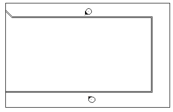
In the last Revit tutorial, we have learned how to split Revit views. We are still discussing about view. In this post, we will discuss how to rotate Revit views. Why would we want to do that? As you see in our last model, the west wing is not parallel to the horizontal axis. There are some reasons why we want to rotate our views:
- First, we want to represent the model parallel to our sheet, not perpendicular to north as orientation.
- Second, we probably want to display it with original orientation, but we want to see it parallel to our screen. Many people (and I am) think it will be easier to complete the model if we have it that way.
For Modeling Only
If you want to display them only for modeling purpose, then we need to create another view. This time an independent view. Just to remind you, you can do it by right clicking the view name on project browser, then select duplicate view>duplicate from context menu. The alternative is you can access Revit ribbon, in view tab>create panel>plan views.

Now you can use this view for modeling purpose.
Remember: you don’t draw on Revit views separately, but building the whole model using views. Any changes in this view will also be reflected to any other views. Whatever you do here, will be shown in the original view. Except for annotations and other 2D detailing objects.
For Modeling and Drawing Representation
If you want to have the model rotated both on the view and sheet, then you can rotate the view directly. You can create an ‘un-rotated’ view anytime by using create plan views. Just in case you need it later.
Rotating View
Rotating Revit view is very easy. You need to show the crop region boundary first. We have done it in the last tutorial.
Click the crop region boundary to select it. With the boundary selected, activate rotate by clicking the tool button on your Revit ribbon.

hint: You can also use RO as shortcut.
You will see Revit is now showing the rotation center and rotation reference.

Move your pointer to the center of rotation, click and hold your left mouse button, drag it to a point on your model. I use our last model as example here.
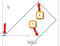
After we move the center of rotation, we need to define the rotation angle. You can type the rotation angle in the option bar, however, sometimes picking the reference points from your screen is easier. Use these points as your reference.
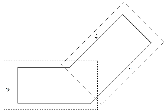
The first point is to define the original object orientation. The 2nd point to define the rotation angle. Now you will see the model in your view rotated like this. You may need to adjust the crop boundary to fit the new view angle.

Remember that we only rotate the view, not the model. If you have the original view, compare it to this rotated view. The original model is not rotated! Take a look to the elevation view symbol too.
Now let us see what happen if we have one of the independent views is rotated.

After rotating your view, now you can work on your model easier. Try to create something and examine your other views.
Adding New Elevation View
It is not common to have our view like this.

Most of the time we want it parallel to our model. You can create a new view and delete the original view. Well, you can try to rotate the elevation symbol too. But to me, it is easier to create a new one.
You can create it by clicking the elevation view. It’s on Revit ribbon>view tab>create panel. When you place the elevation symbol to your model, you will see it still use the north as orientation. Press [tab] several times to make it parallel to your model, then click to place it.


