In this Article...
Every AutoCAD user is aware of tiny blue dots associated with most of the drawing components yes I am talking about multifunctional grips, most of the time you must have used them to make minor adjustments or manipulations in the drawing like stretching and changing lengths but little are aware that a multifunctional grip can be used to perform more than that and it can be used in a variety of ways that can enhance your productivity and also reduce time in making a drawing so here I will tell you how a multifunctional grip can be used to perform tasks without using their command equivalent.
Modifying Drawings:
Make a rectangle and select it so that its multifunctional grips are highlighted now go to any of its multifunctional grips and click on it the color of multifunctional grip changes to red and on your command line you will see **STRETCH** as shown in image.
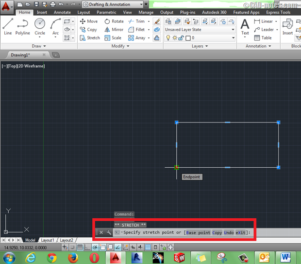
Now go ahead and press enter or space bar and the command line will now show MOVE press enter again and it changes to SCALE and then MIRROR so you can basically perform all these commands using multifunctional grips without even going to any of these commands, let’s now explore each of these commands I will use rectangle to explain these tools in the examples below.
USING STRETCH:
Click on any of the midpoint multifunctional grip the command line now reads **STRETCH** specify direction in which you want to stretch your rectangle and enter length that you want rectangle to stretch and press enter the rectangle will acquire new stretched length you can use similar method for other geometries as well.
USING MOVE:
Simply specify the direction in which you want to move your rectangle and specify distance the object will move to new location you can also move rectangle dynamically by moving cursor and placing on desired location using multifunctional grips, to make a copy of object instead of moving it select COPY from sub command which appears in command bar, You can also change base point of rectangle using subcommand.

USING ROTATE:
Here also you can use multifunctional grip to specify direction dynamically or enter angle in command bar angle will be measured in anticlockwise direction from positive side of X axis, you can make copy of this rectangle while rotating or change the base point using options available in subcommand.
USING SCALE:
Just like previous options you can use scale too select the multifunctional grip which you want to make as base point and drag your cursor to dynamically scale rectangle you can also specify numeric value of scale in command line. COPY and BASE point options can also be found in this situation as well.
USING MIRROR:
Here you need to specify second point of mirror line as the first point is multifunctional grip itself, and to make a mirrored copy of rectangle select COPY from subcommand otherwise the after mirroring original rectangle will get erased.
Modifying Hatches:
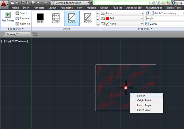
When you select an associative hatch you will find one single multifunctional grip at the center of hatch go ahead and hover your cursor over that multifunctional grip you will find a menu which is similar to the image below let’s explore options of this multifunctional grip menu.
Origin point:
When you hatch over an area the hatch pattern is applied to it without prompting you for a specific start point of hatch but if you want to indicate a start point for hatch so that patterns are placed uniformly you can use origin point to indicate where the origin should be taken in order to make the hatch, the following image will make this point more clear.

Hatch angle
To change the angle of hatch pattern you can select this option from multifunctional grip menu note that the default angle of hatch pattern is considered zero no matter what its inclination is for example in this case of ANSI 31 Hatch pattern the hatches are incline at 45 degrees but AutoCAD will assume this to be zero degrees similarly if a pattern has vertical hatch lines then that will be considered zero for hatch angle consideration as it is the default pattern, In this case the default hatch angle can be changed dynamically by selecting hatch angle option and the hatch angle will change with your cursor click on screen to keep the new angle where you want or enter new angle in command bar and press enter.
Hatch scale
It is the separation between hatch lines or patterns you can increase or decrease hatch scale using this option dynamically, select this option now move your cursor away from multifunctional grip to increase scale and also you can move your cursor towards multifunctional grip to decrease hatch scale click on screen when you are satisfied with the hatch scale or enter numeric value of scale in command bar and press enter.
Modifying Dimensions:
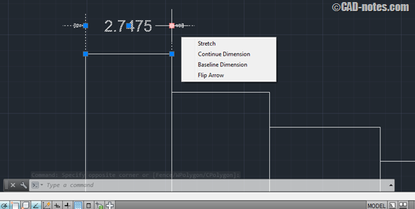
You can use multifunctional grips to modify dimensions as well let’s explore some of the options associated with dimension multifunctional grips. In the image shown below you will find four sub options in the menu which appears when you hover cursor over one of the multifunctional grips near dimension arrows.
Stretch
You can use this option to stretch placement of dimension on drawing area, select stretch then move your cursor in drawing space and click on new point where you want to place your dimension.
Continue dimension
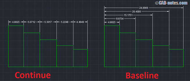
To make dimensioning clutter free a method of chained dimension is used where each subsequent dimension starts from end point of last dimension if you want to apply this method of dimensioning select ‘continue dimension’ and keep clicking on next points to make chained dimensions.
Baseline dimension
In this case the dimensioning starts from one point and all the subsequent dimensions are measured from that point only to make these type of dimensions select ‘baseline dimension’ the first point of primary dimension will become base point and keep clicking on subsequent points dimensions will be added measuring from initial base point the following image will clarify difference between baseline and continue dimension.
Flip arrow
Here in this image you can see that both the arrows are pointing towards dimension value to change direction of any of the arrow hover the multifunctional grip over that arrow and select flip arrow the direction of arrow will get reversed.
Other multifunctional grip options associated with dimensions
When you hover your cursor over multifunctional grip near dimension text you will find multiple options which are self-explanatory I suggest you to explore these options yourself they might come in handy for minor adjustments and giving final touch to your dimensions.
Multifunctional grip associated with spline:
You can convert a spline (FIT) into spline with control vertices and vice versa by picking this arrow multifunctional grip and selecting “Fit” or “control vertices” from sub-options menu, this image will make things more clear.


Great tips! I also find myself selecting more than 1 grip at a time. You can select multiple grips by holding shift while selecting them. ( After the Object has been selected )
I would like to turn a “toolbar” or “ribbon” on so I can have my osnaps on the screen at all times….please direct me??? thanks
You can show object snap toolbar by typing below command on command line. When you type the toolbar name remember to use double quote because AutoCAD won’t accept space in command line.
Command: -TOOLBAR:
Enter toolbar name or [ALL]: “object snap”
Enter an option [Show/Hide/Left/Right/Top/Bottom/Float]