In this Article...
MicroStation levels are used to separate and distinguish your drawing objects. When the drawing become complex, you will need to control the object appearances. You will need to show them in different colors, different line weight, and different line style… or you may need to show/hide objects in a certain category. You can use levels and their attributes for this purpose.
You can group object in the same category in a level. This is probably has the same concept with reference files (will be covered later). Imagine you draw in a paper. After you have done, you want to add more objects in different category, but you don’t want to mess your previous drawing. So you take a transparent paper and place it above your previous drawing. You draw on that transparent paper. When you need to see the original drawing, you simply remove the transparent paper. But when you need to see the complete drawing, you place the transparent paper. When your drawing become more complex, you will need more transparent papers. Each paper is level. And unlike the transparent paper, MicroStation levels are much more convenient and virtually unlimited. Not really, but I believe you will never use more than MicroStation has provided.
Managing Levels and Controlling Level Display
MicroStation Level Manager
You can create, delete, and manage your levels in MicroStation level manager. To open level manager, you can access MicroStation menu: Settings>Levels>Manager. You can create a level, rename it, and change its attributes. You can also see whether the levels are used in your drawing or not.
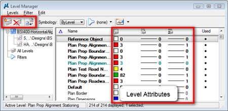
You can only delete level that is not in used. When the level has bullet in used column, then you can’t delete it.
You can rename and change the level attributes by clicking on desired column. In this example, you can choose the line style from the pop up menu.

MicroStation Level Display
If you are an AutoCAD user, you can control the level display on/off in the AutoCAD layer manager (level in MicroStation is layer in AutoCAD). But not in MicroStation. You turn them on/off in MicroStation level display window. You can open it by accessing MicroStation menu: Settings>Levels>Display.
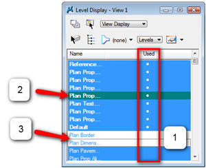
You can see which level is used (has objects on it) in the used column (1). The used levels have bullets in the column. The active level is highlighted in green (2). Active level is where your objects will be placed when you use drawing tools. The hidden levels are shown in white (3), while the shown levels are highlighted in blue.
Changing MicroStation Active Level
There are several ways you can set the active level:
- From level manager or level display, right click above desired level and choose ‘set active’
- From key in window, type ‘active level LEVELNAME’. Change the LEVELNAME with the level name you want to use.
- Choose the level from attributes toolbar.

MicroStation Level Attributes
MicroStation has many level attributes. By default, it will only show you three attributes: color, line style, and line weight. Open level manager, right click above an attributes title bar and you will see the complete list of level attributes. You may not need all of them, but when you do, click the attributes to show it on level manager.

By Level Properties
By default, object attributes will use ‘by level’. It means your object will use the attributes you set for the level. However, you may need to override the attributes when you place your objects. You can do it from attributes toolbar.
Color
The color usage should be clear. When you need to distinguish your objects, color is the easiest attributes to be noticed. And of course, if you want to print in color, you will want your objects to look nice by using colors.
Line Style
MicroStation has two types of line style: standard or custom. The standard line styles are mark by number: 0 to 7. While the custom line style are using names.
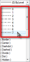
The difference between those two is the standard line styles are just symbolic, and the custom line styles act like actual objects.
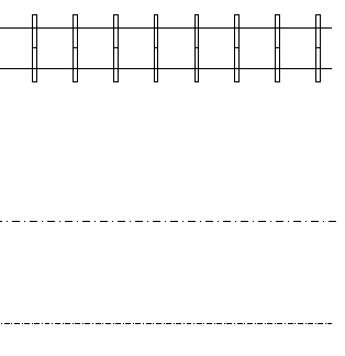
Take a look at this example, all of them are SmartLine with different line style. The first one is using custom line style: rail road. The second is using standard line style no.4. And the last one is using custom line style: dash dot.
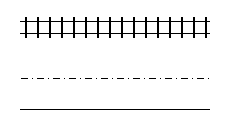
After I zoom in those objects, you can see that the rail are also looks bigger. The 3rd line is now showing dash dot. But take a look the 2nd line. It still maintain the dash dot size. Doesn’t matter if you zoom it very close, you will still see it at that size. Standard line style is very useful for annotation and symbolic lines. For example: object center lines.
Line Weight
Color is probably the best way to distinguish your objects category. But most technical documents are printed in black and white. To distinguish your objects in black and white documents (and we also use it in manual drafting) is using the line weight. There are 32 line weight you can use, from 0-31. The number is just index, not actual weight (just in case you are thinking 31 is 3.1 mm or something, like I was before). You can map the actual pen weight later when you print.
We will try a simple exercise later.


Hello, I am having a major issue with my saved settings. I will have all of the necessary settings active that I want but a lot of the time when I go back in to my drawing the levels that I saved as on are off again. I have saved settings upon exit clicked in my preferences and I will even do save setting manually before leaving my drawing. I do not know how to fix this issue. Could it be an issue with Microstation and Projectwise working together? Please advise!!!
Hi Edwin, I use projectwise and want to print the hatch area with lighter color, but could not make it happen. Please advise. Thanks a lot!!
Hello,
My levels have colors and weights assigned to them, but when I go to switch the level I want to draw in, the color and line weight do not change with it. I will draw a line, and it will be in the correct level, but not the correct color. Thoughts?
What i do not understood is iif truth be told how you’re no longer actually much more neatly-appreciated than yyou
may be now. You are so intelligent.
Dear Edwin,
I really would appreciate your help in this guidance about MS. It is very useful indeed.
Best Regards,
meri
Hi Phan,
I believe you mean V8i. There is a mapping tool for level. You can convert the levels to any level you want to.
But I don't have access to MicroStation anymore, so I can't try it or give detail about it. I'm sorry about that.
dear Edwin,
I have 12 .DXF files, I have to create one .DGN file having all .Dxf files into it as levels with attribute Data. I have no idea how to do it. Please help if possible
Dear Edwin,
i am new to MS , i have 2d layout of car plant i have to build 3d in MS can to plz tell me the path by which i can get standard items like fence , worker ,tables , turn table , tip dresser , robot etc
i hope you will get me solution for my problem
best regards ,
rao
Dear Edwin,
I'm new to MS; will be using both ACAD and MS from now on. I use custom color for the background (light grey). ACAD automatically switches color of white lines to black when the background color is different from black.
MS does it automatically for the white background only. Is there a semi-automatic way to do it for other colors?
Hope you have a solution for me.
best regards,
mp
Mark,
Unfortunately I don't know how to do it. I'll do some searching and inform it to you if I find anything that can solve your problem.
Fire Fighting Text Level number not available to OFF the level from drawing sheet.(this is my problem how to solve please sir