Master skeleton is not a feature in Autodesk Inventor. It’s a design trick and usually called Top-Down Design Concept. It is useful for controlling shapes and dimensions to assemble complicated parts. And simplify modification for entire assembly design.
For example is in a complete design of Aseptic Tank.
Master skeleton consist of one or more sketches with dimensions or parameters that are linked to each other. Using constrain in drawing sketch for master skeleton is required to determine relation between entities or sketches. Then the sketch becomes master skeleton we use as reference of part drawing. Later, it will be a component of one unit of assembly.
Furthermore, another benefit of using master skeleton as design concept is to ease a drafter assembling parts that have been made, because it needs only two constraints which are flush and mate.
However, the draftsman should be more careful in making parts from master skeleton reference. Especially in ‘direction’ feature, because it can give wrong result.
Now we will make simple assembly from a master skeleton concept.
[Practice] Simple Parametric Tank
We will create a simple parametric tank as an exercise. This simple tank consists of Top part, Bottom part, Shell and Support. Support can be Bracket or Foot shaped. Follow these steps.
1) Creating master skeleton
a. Click “New” ![]() on “Get Started” tab and choose “Sheet Metal (mm).ipt”, then click “Create” button on lower section of “Create New File” dialog box. Blank window will be opened and we are ready for creating new part.
on “Get Started” tab and choose “Sheet Metal (mm).ipt”, then click “Create” button on lower section of “Create New File” dialog box. Blank window will be opened and we are ready for creating new part.
b. Click “Create 2D sketch” ![]() then choose plane where we will locate the sketch. For example, choose “YZ plane” on model browser.
then choose plane where we will locate the sketch. For example, choose “YZ plane” on model browser.
c. Choose “Project Geometry” ![]() on “Draw” panel in “Sketch” tab. Then choose “Centerline” in “Format” panel. Then choose “Y axis” on model browser. Right click and choose “ok”. Continue same procedure to set horizontal reference, for example Z axis.
on “Draw” panel in “Sketch” tab. Then choose “Centerline” in “Format” panel. Then choose “Y axis” on model browser. Right click and choose “ok”. Continue same procedure to set horizontal reference, for example Z axis.
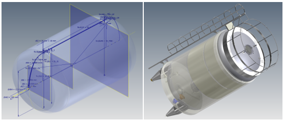
d. Create sketch like picture below using features in “sketch” tab.

Because simple tank consist of some parts, to ease model creation, every part should be created in one sketch. Create those sketches in the same plane.

To make sketch that has been a reference before, you can use “Project Geometry” command, as has explained before.
To name dimension, we can do it by typing name and dimension’s size that we want when we make it.

To end every sketch you’ve created, you can click “Finish Sketch” ![]() command in “Exit” panel .
command in “Exit” panel .
After all sketches have made, save this file as “Master Skeleton”.
2) Managing Parameters
a. Choose “Parameters” ![]() command in Parameter panel on Manage tab. Then parameter dialog box will show up like picture below :
command in Parameter panel on Manage tab. Then parameter dialog box will show up like picture below :

On “Model Parameters” section, in “Parameter Name” column, names you’ve created will be shown. Check on “Export Parameter” column.
b. Expand “Parameters” panel on “Manage” tab then choose “Export to XML”. Export to XML dialog box will be opened. Save that file with name “Master Skeleton Parameters”.
3) Creating Model from Master Skeleton
a. Create new file to start creating new model. Click “new” in Application menu ![]() . Choose metric templates, then choose sheet metal (mm).ipt.
. Choose metric templates, then choose sheet metal (mm).ipt.
b. Click “Derive” ![]() on “Create” panel in 3D model tab. Then “open” dialog box will be shown.
on “Create” panel in 3D model tab. Then “open” dialog box will be shown.

Choose master skeleton that you’ve created before. Click “Open” in “Open” dialog box. Next dialog box will show is “Derive Part” dialog box.

Expand “Sketches” and “Parameters” on “Derive Part” dialog box.
On “Sketches”, click (+) sign ![]() to exclude Shell sketch, Top part sketch & Legs sketch. The symbol will be like picture above.
to exclude Shell sketch, Top part sketch & Legs sketch. The symbol will be like picture above.
In “Parameters”, all parameters that you have created will be shown. Make all their status to be active.
Click “Ok” button on lower area of “Derive Part” dialog box. The window will show Bottom part sketch.
c. Click “revolve” on “Create” panel in “3D model” tab. Revolve dialog box will show, then choose sketch available as profile and Y axis as revolve axis.

Click “ok” to end revolve command.
d. Click “Thicken/Offset” command ![]() in “Surface” panel on “3D model” tab, then “Thicken/Offset” dialog box will show. Choose all the surfaces and input 2 mm in the “Distance” with direction as picture. Click “Ok” to end command.
in “Surface” panel on “3D model” tab, then “Thicken/Offset” dialog box will show. Choose all the surfaces and input 2 mm in the “Distance” with direction as picture. Click “Ok” to end command.

Right click on “RevolutioSrf1” and choose “Visibility” to make the surface become invisible. The mode arranged will show like below :

Save the file with name “Bottom Part”.
Create other parts like Shell, Top part, and Legs in same way by using features available at 3D Model tab.
![]()
Now we have these files :

4) Assembly Modeling
a. Click “New” on Application Option, then choose “Metric” templates and choose “Standard(mm).iam”. After that, click “create” button to create an assembly.
b. Choose “Place” on “Component” panel on Assemble tab, then “Place Component” dialog box will open. Choose Master Skeleton for first part that will be assembled, then choose “Open” on lower area of “Place Component” dialog box.
c. Expand “Origin” and “Folded Model” master skeleton part in browser like picture below.

d. Click “Constraint” on “Relationship” panel in “Assemble” tab, then “Place Component” dialog box will open. Choose “Mate” ![]() in “Type” column and “Flush”
in “Type” column and “Flush” ![]() in “Solution” column. After that, choose origin plane on both Master Skeleton and Assembly model.
in “Solution” column. After that, choose origin plane on both Master Skeleton and Assembly model.
If you choose “YZ” plane on Master Skeleton, you should also choose “YZ” plane on Assembly model.
e. Continue constraint allocation on three planes so that it’s fully constrained. Add another parts that have created with same constraint to Master Skeleton.
f. Right click on master skeleton, then choose “BOM Structure” and choose “Reference”. Then make the Master Skeleton become visible too.

So it looks like this :

5) Managing Parameters and iLogic Rules in Assembly Model
a. Click “Import from XML” in “Manage” panel on “Manage” tab. Open Master Skeleton-Parameters have created.
And see that parameters you have made in Master Skeleton will be copied into User Parameter Assembly.

b. Show “iLogic” browser by clicking “iLogic Browser” panel in “Manage” tab .

Click “Add Rule” on the same panel and tab, and name it Simple Tank Rule. Then “Edit Rule” dialog box will open.
c. In Principe, if we’re going to change dimension in Master Skeleton, we can change it directly in Assembly model. Inventor will synchronize parameters between Assembly model and Master Skeleton. So if we change dimension in Assembly model, dimension in Master Skeleton will also change. And we won’t be able to change dimension in Master Skeleton without deleting relationship between parameters that have made in Assembly and Master skeleton.

d. On “Model” tab expand Master Skeleton then click on “Model Parameter”. Parameters in Master Skeleton will be shown in right column. Double click on “Parameter” column to open in iLogic editor.
Then do same thing on parameter assembly placing it in the same name.
Click “Ok” in “Edit Rule” dialog box.
6) Make Form to Modify Model
a. Click “Forms” tab in iLogic Browser. Right click on empty space in “Forms” tab and choose “Add Form”. Then Form Editor dialog box will show.

b. Click “Form 1” in Label column and enter new name to rename the form. Rename the form with Tank Modification.
c. Choose “Renamed” parameter in parameter check box.

d. Drag all parameters in “Parameters” tab to “Label” column, and rename it like picture below.

Click “OK” button to finish this section.
e. Now, if you click “Forms” tab in iLogic Browser you will find “Tank Modification” Button. Click “Tank Modification” button, then Tank Modification dialog box will show, and you can modify the tank by this form.

f. Try to change Inside Diameter Tank to 700mm, Shell Height to 400mm and Legs Height to 500, and see the changes.

Now, you can control dimensions of parts you filled in Tank Modification form. When you input dimensions, make sure it’s rational numbers, so it will form proportional tank. Alright then, have a nice try!!


Hello Andriana Teja, I have one question on iLogic part of Autodesk-Inventor, if you have a background on that I would like to get your help in one of my task?
Hi Andriana Teja, The links for the parametric model are dead, could please upload the model including the ilogic rules?
Thank you in advance
Hi.. please would you send me the skeleton file
Very interresting tutorial, im new in this subject.
I have some troubbles with see the picture of the tank, and i cant download the file u senden – is it possible you can send a screenshot?
Interesting tutorial – any possibility of screenshot of the master skeleton that is legible?
Thanks Mike. If you have a trouble with that screenshot, you can download Master Skeleton file here http://www.sendspace.com/file/85otsu
Can you send me the file of this tutorial?
Dear Lambertus,
Please find the file in link below :
https://www.sendspace.com/file/4qkcb6
great job brother, is it possible in assy drawing I can switch my top head vessel from toriconical to ellipsoidal or vise versa?
Thanks Dwi…I think that possible to do. We can use iLogic to control that function but it need more time because we must create all part or all variation assembly in one and any variation codes for iLogic.