If you read CAD Notes tutorial on dynamic block, we use wipeout to automatically ‘trim’ objects. Very useful for placing door on a wall or schematic drawings.
However, wipeout has a downside. Some people reporting that wipeout won’t plot correctly on some plotters or to pdf format. I tried it, and don’t have any problem with wipeout. But if you have the problem, then what else can you use to do that trick? We can use solid hatch!
You can try to activate hatch, then select solid pattern. Then in color selection, you can choose the color to white. But where is the white color?
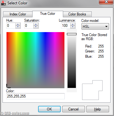
White color is not available in indexed color. Click the color list then choose select color.

Now you can see that default color is indexed color… and it has no white. But if you go to true color, you can find the white color. Move the luminance slider to the top or change the value to 100. You will get white or 255,255,255.

Now you can use it to mask object beneath your object.
Do you know that you can also have background color for hatch? This only available for pattern. You can mask object below your hatch, and show it more clearly.

If you still have problem with plotting hatch masking in pdf, you can see the explanation of ‘streak’ in here.


I need to overlay an editable text block designator in schematic drawings (over P-Lines) and I don’t want to “break” the P-Lines on each side of the text over and over again. I would rather the P-Line just be hidden “under” the text block. Can this be done with Wipeout or some Hidden Hatching of some sort to mask the P-Line AND at the same time have the WO or H block used to hide the P-Line masked as well?
And if I edit the text designator, will the WO or H “follow” the text length?
Any help would be appreciated….
Dan,
How did you create the text block? If you use MTEXT, there is option for add “mask’ for the text.
Thanks for this tip. I found that the 255,255,255 mask works well if you it in conjunction with the draworder (‘DR’) command. This allows you to adjust the ‘level’ that the mask resides within the DWG.
Thanks Clint, works great!!!
I too have had issues with wipeout plotting incorrectly in pdf files. Wipeout actually creates an image which blocks whatever is below it. There must be something in the way pdfs read that image that in my case creates a solid black object. My work around was to create a seperate layer to set my wipeouts on,0-wipeout and set the pen to 255 with screening set at 10, this results in an imperceptible gray that does not show in pdf and works well with our plotters. Just be careful not to set the layer to NP or freeze it, because then the wipeout will not show up at all and not block what was intended. I can see where thehatch may work better in some cases, since it will follow curves where as a wipeout only works with straight line segments. I find wipe out great for windows, doors and railings because I can hatch my surface and then place a block over it containing a wipeout and not have to wory about a gazillion islands in the hatch.
Thanks for sharing this Clint!
I never think about using this trick. Maybe the others can use it.