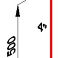
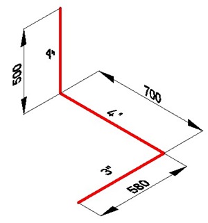
 I have posted a couple tutorial how to draw isometric drawing and dimensions. If you look at the dimensions closer, there’s something not right. The dimensions are still using the default style, which is not isometric at all.
In this post, we will create a new arrow to fix this. You can use this technique to create your own later. But now, we just use it for isometric drawing. The original post was written in Indonesian by Pither Rukka, one of our contributors.
First, you have to create a drawing, how you want your arrow look like. I create something like below. Make it pointing to right. You may want to use ellipse or something else. You can also use lines, arc, hatch pattern, etc. But let’s create something easy first.
Three things you can use as a guide when you draw it:
- Use angle about 30deg, because it is the default angle for isometric drawing in AutoCAD.
- Draw a dimension using existing style. Refer to the default arrow for your drawing size.
- Now related to #2, check your dimension style. You have to create the drawing as large as size 1. If you have your referenced arrow size 100 in your style, then resize your drawing to 1/100.

Create it as an AutoCAD block. Define your insertion point like below.

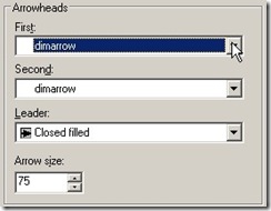
Now open dimension style dialog box. Modify your isometric dimension style, in symbols and arrows tab, change your first and second arrow heads to user. Then select your block.

Check your drawing now.

Looks better. But there is something still not right. Take a look at dimension showing 700 value. It’s not supposed to look that way. How to fix that?
Well, there is no other way. Just like before, you have to create another style for it. Want to try it by yourself?


For some reason when I use a user arrow, the line that comes out of the end of the arrow no longer comes all the way to the arrow, there is a gap between the arrow head and the line (I am using an architectural tick, instead of an actual arrow). What's going on here?