In this Article...
Last week, we have cover a little about conceptual design. This time, let us talk a bit more about conceptual design: how we can work with free form modeling in Revit. This functionality added in Revit Architecture 2010. We can easily stretch faces, edges, or points to do free form modeling. This is quite nice and very easy to do. In this tutorial we are going to create a loft then try to use this capabilities.
Creating the form
Before we start, let us try to create another mass family. We need to create a form before start using the free form capabilities.
Creating Base Profile
This time, I start creating a rectangle with size 50.000×100.000 mm (it means 50m x 100 m).
I want to create a loft, so I need to add at least one more profile before I create a form. We need the second profile a few hundred meters above the first profile, so we need to add a plane as the reference for the profile. We need to add the plane using elevation view, so open an elevation view. You can choose east, west, south, or north view. It doesn’t matter.
Creating Reference Plane
To create a reference plane, you need to activate the plane tool in draw panel.
Add the reference plane 200m (or more if you wish) above level 1.
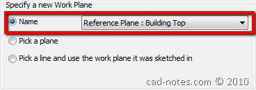
Now we have the reference plane. Rename the plane as ‘building top’. Now, let us choose it as the active plane. Click set in work plane panel.
Choose the plane we created in the previous step then click OK.
Additional Tips: Set the Floor Plan View Range
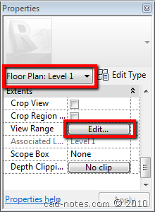
This is a high rise building that beyond the floor plan view range. We only have one level here. When you try to create using level 1 view, you may see a warning that your element will not be displayed. Change the family to Floor Plan: Level 1. Find view range parameter and click edit button.
Revit will open a dialog box. Make sure the reference plane is between cut plane and top range.
Click OK and we can start to work.
Creating Top Profile
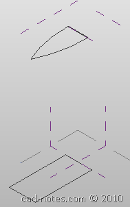
Now that we already set the active plane to the building top, we create the profile on this elevation. Draw a close profile similar like this. The actual size is up to you.
Not so difficult, right?
Creating Loft
We already have two closed profile. They are enough to create a loft. Activate modify tool and choose them both. Remember, you need to hold [ctrl] to select multiple profile. Click create form.
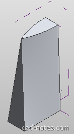
Now you should see the form created like below.
Working with Sub Objects
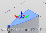
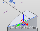
Let us play around with free form. Activate modify tool and click the surface. You will see the gizmo (the XYZ axis) appear at the surface center. You can click and drag the gizmo to move the surface. You can also activate modify tools like scale, rotate, etc. Don’t forget to give edges and point a try :)
 |
 |
 |
| Surface Selection | Edge Selection | Point Selection |
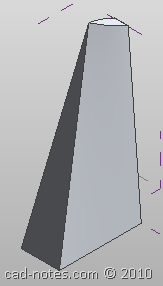
This is what I get after I scale the top surface, and drag the point up.
Save your conceptual mass. We are going to explore more about conceptual design later. Feel free to continue exploring this free form capabilities.
As usual, you can see the video on CAD Notes YouTube channel.
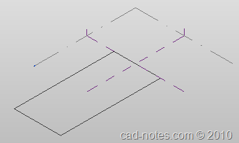

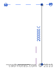





You should add that there are differences to how your mass will behave if you create it with reference lines instead of model lines.