In this Article...
You have learned how to provide coordinate input in AutoCAD, and using AutoCAD drafting tools. Let us do a little exercise before continue to the next topic. We are going to use some AutoCAD drawing tools and drafting tools.
Using the Metric Template
We are using metric template for this AutoCAD tutorial. If you haven’t set the default template to metric, create a new file from AutoCAD menu: new>drawing. Do not click the new file button on quick access toolbar! The button will use the default template and AutoCAD will not ask you which template you want to use. Select acadiso.dwt as template then click open.
Using Drawing Tools
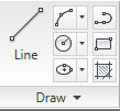
You can access AutoCAD drawing tools on AutoCAD ribbon, home tab, draw panel.

Activate rectangle.
To Input Coordinate
Click anywhere on your screen. The active field should be X field.
- Type 50 to define 50 units to the right (the X positive). Press comma. This will lock the X value and move the active field to Y field.
- Type 150 then press enter. This will define the second point Y value 150 units up (Y positive).

You just define a rectangle by defining X and Y value.
Using Object Snap Tracking
Activate rectangle again
Hint: You can press [enter] to reactivate last tool
Move your pointer above the right-bottom corner of the previous rectangle. Wait for a moment and move your pointer to the right. You will see dashed line and the dynamic input mentioning ‘extension: DISTANCE<ANGLE’. Move your pointer horizontally, sticky to the X axis. Type 700 then press [enter].
![]()
Type 50,150 [enter] to define the next point.
You’ve just created another rectangle by defining the distance from another object.
Using Object Snap
Activate rectangle again. This time snap the first point to the top right corner. Click to define the first point.

Type 30,700 [enter] to define your rectangle.
Creating Arc
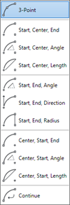
AutoCAD has many method to draw an arc, depends on what points do you have as references.

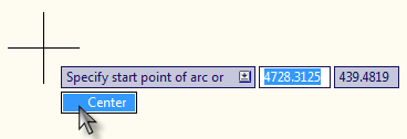
This time click the 3-point method. Pay attention to what AutoCAD is asking you. Specify start point of arc or ↓

The down arrow is showing that there are options related to this tool. Press down arrow. There is one option for this tool: Center. Select it.

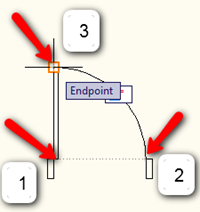
Now AutoCAD is asking for center point. Click point 1 as the center point. Point 2 as start point, and point 3 as the end point. If you draw arc using start-end point, then AutoCAD will draw it counter-clock wise.

Hint: You can use command line to change option. Type the capital letter to choose available option then [enter]. If there are more than 1 character in capital letter, type all of the capital letters.
Specify next point or [Arc/Halfwidth/Length/Undo/Width]:
Nothing hard right? :) When you draw with AutoCAD drawing tools, you will only need to change options if necessary, then define the points. Look for some drawing samples and try to draw it. You may submit your inquiry here, probably I can help.
Next, we will learn to use modify tools.


You are amazing, like your tutorial
Thank you So Much for giving us such great knowledge
thank you very much
thank you very much..