We created a simple MEP model in our tutorial series. Now we are going to examine and analyze our MEP model. We cover several tools that can help you to examine your model.
Show Disconnects
First, let’s check if our model has any equipment or routes that are not connected yet.
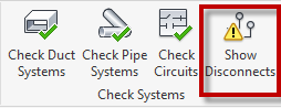
On Revit Ribbon> Analyze tab> Check Systems tab, click Show Disconnects.
In the Show Disconnects Options, check the category that you want to examine. In this example, I only activate the pipe category. If you have a complex model, it is easier to check each category separately.
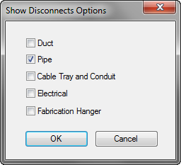
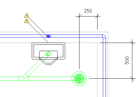
Click OK. If there is any route that is not completed yet, you will see the warning. After you connect the equipment, the warning will disappear.
System Inspector
Now let’s examine the flow information. Move your pointer on a domestic cold water pipe then press Tab until you see “Branch in a pipe network up to a piece of equipment” on the status bar or on the tooltip.

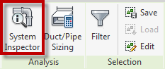
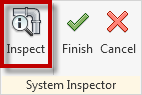
Click to select the pipe. After you select the pipe, on the contextual tab, you can see System Inspector tool. Click it.
Click Inspect on the floating panel.
Move your mouse pointer on a pipe. You can see the flow arrow and volume on your pointer. You can place a temporary tag to compare the value to another pipe.
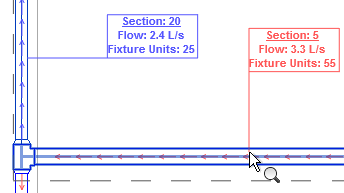
After you finish, click Finish on the floating panel.
Pipe Pressure Lost
You can generate Duct or Pipe Pressure Loss Report quickly. On the Ribbon> Analyze tab> Reports & Schedules panel activate the tool that you want to use.

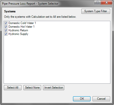
Revit will show you a dialog to choose which system to generate the report. Select the systems that you want and click OK.
Next dialog is the Pipe Pressure Loss Report Settings. Select which fields to include in the report.
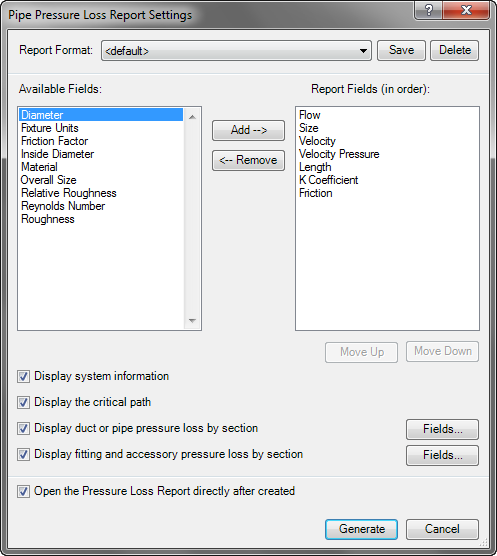
Click Generate and save the file. Examine the generated report.
Pipe Fill Legend
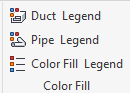
On Revit Ribbon> Analyze tab> Color Fill panel activate Pipe Legend.
Click on an empty area to place the legend.
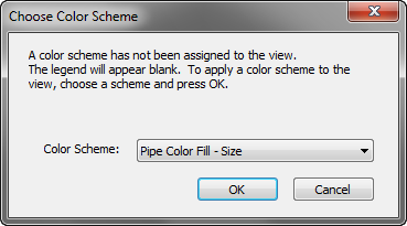
Revit will ask which color scheme that you want to use. Select the color scheme that you want then click OK.
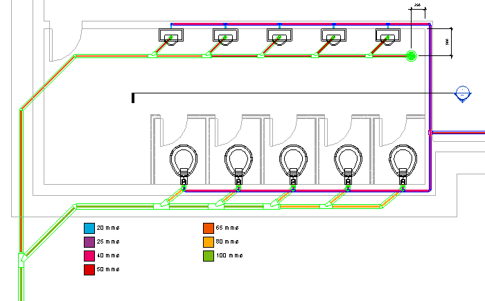
Now the drawing shows different color for different pipe sizes.
To change the color scheme, select the pipe color legend then click Edit Scheme on the contextual ribbon.
Summary
Revit has several tools to check your model easier. You can easily find disconnects, check the flow, pipe pressure loss, and check it by a color scheme. The tools are very easy to use but give significant help. You can use the tool at any stage of your design to validate your model. It is easier to check the model gradually than the whole model after it’s finished.


This is a common feature that we explain in our training to find disconnects when building a system.