• Home
  • Training Books
  • Subscribe to Our Email Newsletter
  • About
    • Contributors
    • Feedback
    • Contact
    • Privacy policy
    • Cookie Policy

CADnotes

CAD Tutorials and Best Practices for professionals and students

  • Featured
  • AutoCAD
    • AutoLISP
  • Revit
    • Revit Architecture Basic
    • Revit MEP Basic Tutorial
  • Inventor
  • MicroStation
    • MicroStation Basic Tutorial
  • CADnotes on YouTube
You are here: Home / AutoCAD / AutoCAD Isometric Text and Dimension

AutoCAD Isometric Text and Dimension

September 10, 2009 by Edwin Prakoso 22 Comments

Previously, I wrote about isometric drawing in AutoCAD. It’s not actually AutoCAD 3D drawing. But changing your cursor orientation will make it easier to draw isometric drawings. But have you tried to annotate your isometric drawings? How about dimensions and text, is it appear properly? No, it’s not. The drawing looks isometric, but not the annotations.

So how can you create isometric annotations?

If you use vanilla AutoCAD, there is no direct or easy way to do it. But a little workaround could achieve what you want.

Isometric Text

First, create two styles. Use oblique angle 30 deg for one style and -30 deg for the other.

obluque

Now place your text (single or multi line), change the rotation to 30 deg or -30 deg. It depends on where you want to put it. See next image as reference.

Specify rotation angle of text <0>: -30

Try to create it with several style and text angle combination. Well, basically these three are all you need.

isometric

Isometric Dimension

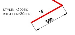
What about dimensions? You also have to create two styles. One of the style use 30 deg text style, and the other one use -30deg.

dimension text style

Now place aligned dimension.

aligned dimension

Now we have to do a little modification.

Activate DIMEDIT [enter], choose OBLIQUE, then give 30 or -30 as oblique angle. Once again, depends where your dimension is.

Command:  DIMEDIT
Enter type of dimension editing [Home/New/Rotate/Oblique] <Home>: O
Select objects: 1 found
Select objects:
Enter obliquing angle (press ENTER for none): -30

See this image as reference.

isometric dimension

Now if you examine the drawing carefully, the dimension arrows don’t look right. They don’t look isometric yet. We will cover this on the next tutorial: how you can create isometric dimension arrow.

I know it’s not fun to do those steps, but it’s the only way if you use vanilla AutoCAD. If you have experience in macro, you can create your own command in CUI or even create an AutoLISP program.

About Edwin Prakoso

I work as a Solution Consultant in Datech Solutions, Tech Data Indonesia. I've been using AutoCAD since R14 and Revit since Revit Building 9. I occasionally write for AUGIWorld magazine and I am also active in Autodesk discussion forum. I'm a member of Autodesk Expert Elite, an appreciation for individuals who give contributions to the Autodesk community.
Connect with me on twitter or LinkedIn. If you want to have my new articles sent to your email inbox, you can subscribe to the newsletter.

Filed Under: AutoCAD

0 0 votes
Article Rating
Subscribe
Login
Notify of
guest

guest

This site uses Akismet to reduce spam. Learn how your comment data is processed.

22 Comments
Inline Feedbacks
View all comments
Jordan
Jordan
10 years ago

How can you get the Isometric Text To lay flat but still at 30 degrees?

0
Reply
Edwin Prakoso
Edwin Prakoso
Reply to  Jordan
10 years ago

Hi Jordan,

Did you mean like this? https://www.cad-notes.com/2009/09/isometric-dimens…

0
Reply
hendy
hendy
10 years ago

hi mr. edwin,
can you tell me how to choose metric or imperial unit to create drawing in one sheet at autocad 2010

0
Reply
alco
alco
10 years ago

GOOD DAY,
As i open a drawing from 2011 autocad, all text (in dimension and block) are only box, how can i see the text in that particular drawing?
Thanks in advance

0
Reply
Edwin Prakoso
Edwin Prakoso
Reply to  alco
10 years ago

Hi Alco,

You can change system variable to see your text.

Type QTEXT, enter. Type OFF then enter again.

Regen your drawing, now you should see the texts…

0
Reply
ktiger
ktiger
11 years ago

You don't need to create the two isometric texts styles. Just double click the dimension text (it's mtext) and set the oblique angle.

0
Reply
Ismailcanli
Ismailcanli
11 years ago

thanks from turkey ;)

0
Reply
Merish
Merish
11 years ago

thanx alot bosss….thanx

0
Reply
syahmi
syahmi
12 years ago

can we make the line or the block obliqued? because i wan to make a 3d look like with the existing drawing.

0
Reply
ThomasB
ThomasB
12 years ago

Thanks for the help. The person here who knows this stuff took vacation and I needed to get the drawing done. Thanks.

0
Reply
moatazabbasccc
moatazabbasccc
13 years ago

good

0
Reply
moatazabbasccc
moatazabbasccc
13 years ago

really it's very good
thankssssssss.

0
Reply
1 2 Next »
wpdiscuz   wpDiscuz
Join Our Free Email Newsletter
  Thank you for Signing Up
Please correct the marked field(s) below.
1,true,6,Contact Email,2 1,false,1,First Name,2 1,false,1,Last Name,2

Featured

What’s New in Revit 2023 part 1: Rebar Enhancements

In this first part of what’s new in Revit 2023 series, I cover about rebar features. Great enhancements in this part!

Recent Articles

  • Revit 2024.1 Update is Released
  • What’s New in Revit 2024: Bending Detail
  • What’s New in Revit 2024: The Dark Theme

Advertisement

New on CADnotes

  • Revit 2024.1 Update is Released
  • What’s New in Revit 2024: Bending Detail
  • What’s New in Revit 2024: The Dark Theme
  • Autodesk Build: Using Assets for Progress Tracking
  • My Home on the ACC Unified Platform

Meet the Authors

avatar for
avatar for
avatar for
avatar for
avatar for
avatar for

Get Connected

CADnotes on FacebookCADnotes on InstagramCADnotes on TwitterCADnotes on YouTube

© 2009 – 2023 CADnotes · Feedback · Privacy Policy · Become an affiliate

wpDiscuz