In this Article...
We have done with creating door basic. We add the main panel and symbolic lines. In this tutorial, we will add more forms: void and solid. As I always said, creating Revit family is just a repetitive process. More complex your object is, more repetition you will do. Not more difficult,but certainly more work!
Open the door you created previously.
Modifying Parameter
We will add a void for the top part of this door panel, and add a glass panel to cover it.
Let us modify a parameter first. Click types button on Revit ribbon>create tab>family properties panel.

This will open Revit family types dialog. Find Frame Width parameter in the dialog.It’s in others group. Others group is at the bottom of types dialog. We will often change this parameter (let’s assume it that way), so we would want it on top. At least along with the other dimensions.
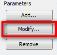
Click modify button to modify its properties.
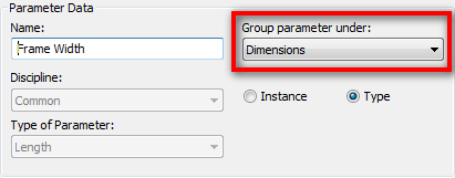
Move the group parameter to under dimensions.
Adding Void
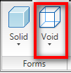
There’s nothing different with placing voids. It’s just like placing a solid form. But instead add the Revit geometry, void will remove your solid geometry. Activate void>extrusion. Void is in Revit ribbon>create tab>forms panel.
Adding the Extrusion Profile
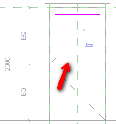
Just like what we did in creating the door panel, draw a rectangular profile like below. Don’t worry about the size, we will adjust it later.
Adding Parameter Dimensions
Now add dimension that measure the rectangle sides to its’ left, top, and right.
After you finish, activate modify tool. Hold [ctrl] and click each of the dimension until all of three dimensions selected.
In Revit option bar, click the label drop down menu and select Frame Width.
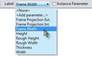
You should see the dimensions become like below. Add one more dimension to measure the rectangle height.
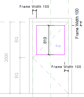
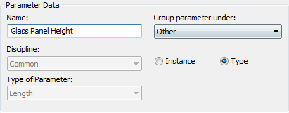
Select the dimension, and from label drop down menu, choose <add parameter…>. Give the parameter name ‘glass panel height’ and put it in other group. This is a dependant parameter, and we don’t want to change the value. So we put it at the bottom of our parameters list.
Creating Formula
Open Revit family types dialog. Find the parameter we just created. Click in formula column and type this formula:
(Height-3*Frame Width)/2
Remember, the parameter name is case sensitive. Do you know why we created the formula, and where are the parameters name come from? And how can we create the calculation?
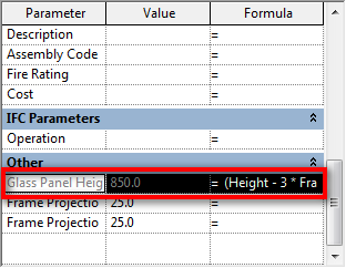
You can see the parameters name in elevation view. Examine them, and find the correlation with our formula. Probably you can create a better formula!
Defining the Void Height
Click the extrusion properties button. It’s on Revit ribbon> create tab> element panel.

Change the extrusion height to 50. Click OK.
Click Finish Extrusion.
Adding Glass Panel
Creating Reference Plane
We are going to add a glass panel at the middle of the door panel. To achieve this, we must create a reference plane first. Open Floor Plan>Ref. Level view. Activate Reference Plane. It’s on Revit ribbon>create tab> datum panel.

Draw a reference plane right at the middle of our door panel thickness.

Select the reference plane, and click element properties>instance properties from your Revit ribbon. Give the reference plane a name.
![]()
Keep in mind that we did not use parameters for our door thickness and this reference plane location. Sometimes we don’t need to give everything a parameter. However, you may use parameters if you feel necessary. Consider this is your extra exercise. We will also discuss about it in the next tutorial.
Creating Solid Form
Now back to elevation view.
Setting Active Reference Plane
Before we start, change the reference plane to the last one we draw. Click set from Revit ribbon>create tab>work plane panel.

In the dialog, find the reference plane, and click OK.
Drawing Solid Extrusion Profile
Draw a rectangle covering our previous void. Try to snap to intersection to make sure the glass will follow the void size.
Remember, try to test it after you create the profile. Change the door width, height, and frame width to see if it works. It is always a good idea to test it after make a change!
Before we finish this extrusion, change the extrusion value. Change the extrusion end to 5 and extrusion start to –5. This will make our glass panel extruded to both direction with the same value.

Click finish extrusion.
Check in plan view, is your glass in correct position?

Challenge
Can you create parameters for frame, door panel, and glass panel? Try it and don’t hesitate to discuss with us!
What’s Next?
We are going to set and define more parameters for this Revit door family. Including material parameters. We will also add one more void, then define several door types.
In the mean time, you can submit inquiries about Revit families. So we can do further exercises, based on your case. This offer is not permanent! :)


Hi Edwin
Would it be possible to explain a step by step process of transfering the information from a AutoCAD title block DWT file to create a new Revit titleblock template file. Thanks
Biswas,
I'll try to write something about it. I hope I can publish it this week.
I like the way you explain things. I have a problem with a couple items.
1-Doing window brick sills and soldier headers
2-Brick around an arch dooror window
Thanks for your help
Hi Vaughn, I sent you an email. Could you provide drawings/sketch of what you want to achieve? Just reply to my email. I'm not really familiar with that terminology… Sorry.