In this Article...
AutoCAD Tips competition has reach the deadline. There are many interesting submission, and as promised, the winners will be announce next Monday. These is the list of tips submitted. However, I do feel that the contestant are not trying to submit their favorite post, but their best tips they can write. Nothing wrong with that, but it makes many people are not willing to submit their tips, and feel it’s too hard. You actually can link to any page on internet where you find interesting tips for you, and not necessarily create your own.
However, the competition has ended. And these are the favorite tips submitted and pass to be selected by the judges.
*This tips order is arranged by their submission time.
**If there are macro or AutoLISP codes, you will need to retype them. This site platform will convert the codes to something else that not recognize by programming language.
1. Load AutoLISP Every Time You Start AutoCAD
If you use some AutoLISP frequently in AutoCAD, you will want to have them automatically loaded every time you start AutoCAD and not reload them every time you start AutoCAD. You can do it by using startup suite.
When you load application with APPLOAD, add your frequently used application to startup suite.

This tip was submitted by Puji.
2. Using Your Own Hatch Pattern
One of the frustration for us, metric users, is many AutoCAD pattern don’t work properly with metric unit. Especially ANSI. Using pattern sometimes is the fastest, for example when we want to create 300x300mm ceramic tile. So we need to create our own pattern for 1x1mm.

Load it in custom pattern tab, and you can use the same scale as you wanted without conversion.
This tip was submitted by Murni Kesuma Ayu.
Some explanation from me:
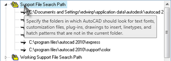
There are also many pattern you can download and probably you also want to create your own :) You need to place the pattern in a folder that’s defined in ‘support file search path’. If you want to create your own folder for better file management, then you will need to add your own folder here.
3. Zoom Extent While Using Tools
When we use a modification command (such as copy, array, etc) sometimes we can’t see the whole drawing and need to REGEN or Zoom Extent. Scrolling your mouse is simply don’t work. Most people will press [esc] quickly, zoom extent, and restart the tool. However, when we use a tool with many properties, this can be frustrating. We need to reset many properties from the start.
We can zoom extent when a tool is active. You can simply click the zoom extent from ribbon (or toolbar).
Additional information: This tip maybe work for smaller file, but it looks like not working for larger files. Probably has something to do with the graphic memory limitation. Thank you for Harold Kip, Harold Weistra, and Gerrit de Jong from AutoCADExchange.com for mentioning this
This Tip is submitted by Setiadi.
Additional Tips From Me
You can also use single quote before Z (‘Z) if you prefer command line.
4. Use Both Hand to Work Faster
It is always faster to work with both hands. That’s why every application has shortcuts. Even many modern web pages has it. So have you used AutoCAD command alias as shortcuts?
This tips was submitted by Halim.
Additional Information From Me
You can see the complete list of these command alias in acad.pgp, and you can also customize them.
5. Switch between Trim and Extend Quickly
While you are working with trim, you can switch to extend quickly, without having to activate other tool and reselect the boundary. You can press [shift] to switch it.
This tip was submitted by Murray Clack
Additional Information from Me
Pressing [shift] when using extend will also switch the command to trim.
6. Use EXTRIM to Trim Quickly
If you need to trim many objects with one boundary (not working for more than one) this is very useful. You only need to select the boundary, then which side you want to trim. All objects crossing that boundary will be trimmed.
This tip was submitted by Ibud Sumardi
7. Setting Grids Within a Limit
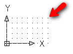
I’m not really sure if many people still using limits at the moment. But apparently it is still useful. If you want to draw using grids, and want your grids appear only within a certain paper size, you can set the limits to do that.
Command: limits
Reset Model space limits:
Specify lower left corner or [ON/OFF] <0.0000,0.0000>:Specify upper right corner <420.0000,297.0000>:
This tip was submitted by Murni Kesuma Ayu
8. Masking in Block Attributes
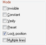
It was impossible to add masking in your block attributes before. But since Autodesk add multiple line features in block attributes, now we can do that.
This of course will take many advantages from multiline text (not all), not just using simple single line text!
This tips was submitted by Murray Clack
Additional Information:
Murray also mention about using fraction and stacking in attributes, but I still can’t manage to use it. I will update this when I can clarify about this fraction and stacking. Probably it was just me :)
To see the stacking button when editing attributes, we need to change the system variable ATTIPE to 1. The detailed explanation is described by Murray in comment. Thank you for Murray for clarifying this.
9. Duplicate Block Definition
When we want to create a similar block from existing block, do you know that we can save the block as? I didn’t :)
This is some thing I missed, and probably you miss it too. This is very useful especially when we are working on a dynamic block with many parameters.
This tips was submitted by Murray Clack
10. Using DIMROTATED Instead of DIMALIGNED
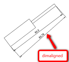
Do you ever have problem when dimensioning when the objects are staggered? Using DIMALIGNED can’t do this. A great tip from Murray mention that we can use DIMROTATED.
There is no documentation or toolbar about it, but I’m sure you will find it really useful!
This tips was submitted by Murray Clack
11. Finally Purge “$AUDIT_BAD_LAYER”
$AUDIT_BAD_LAYER is a layer created when you run audit tool. This layer is kind of persistent and looks hard to remove. But actually.. it is very simple:
To finally purge that annoying $AUDIT_BAD_LAYER layer, simply do the following:
1. Run the AUDIT command
2. Run the PURGE command to get rid of the $AUDIT_BAD_LAYER layer
3. SAVE the drawing and QUIT
4. Reopen the drawing, and the $AUDIT_BAD_LAYER layer will be gone!
This tips was submitted by Murray Clack
12. Navigate Between Model Space and Paperspace with Hyperlinks
Below is a step-by-step process that helps you quickly navigate between Modelspace orientations and multiple Layout tabs using Saved Views and Hyperlinks (this tip is lengthy, but so worth the effort).
- While in a Layout tab, use the VIEW command to save a view name (usually, I would name the view based on whatever the sheet number would be, like “A101”)
- Then, draw a closed pline around the perimeter of a Viewport (either on Layer “defpoints” or a unique layer set to “no plot”), and then use the CHSPACE command to send the pline into Modelspace through that Viewport.
- With your cursor still within Modelspace via inside the Viewport, save a new view name to something reflecting what is going on within the viewport and including the sheet number (eg. “Plan 1 – A101”), and then bring your cursor back into the Layout environment (ie. PSPACE command)
- Enter the command HYPERLINK
- When prompted to “Select Objects”, select the Viewport boundary that you just saved a view in.
- When the “Edit Hyperlink” dialog box appears, click on the “View of this Drawing” button
- Expand the Model tree by clicking on the “+” symbol, select the view name you just created, and then click the OK button
Now, hold down your Ctrl key, and click once on the Viewport boundary with your left mouse button. AutoCAD will then switch to Modelspace and zoom into the area of the saved Modelspace view that you created earlier – and you will also see the closed pline that you sent through the Viewport.
To get back to the Layout tab, repeat steps 4 through 7, but this time, select the closed pline and select the saved view for the Layout.
This tips was submitted by Murray Clack
13. Create a Circular Wipeout
As you may or may not know, you cannot create a wipeout using a circle, only a closed pline without any arcs. Instead, use the POLYGON command.
- Enter the command POLYGON,
- When prompted to enter the number of sides, enter a value of 36 which will create a closed pline that looks just like a circle.
- The use the WIPEOUT command like you normally would, and select the 36-sided pline
I use 36 sides because it looks just like a circle without having too many vertices that make the closed pline too “busy”
This tips was submitted by Murray Clack
14. The Basic of Using AutoCAD Tools
This tips was chosen by Egyherlim, he is referring to a post in CAD Notes: The basic of using AutoCAD tools. He said this is very useful for him when switching from UG NX to AutoCAD. I’m surprised that he was switching to AutoCAD (not Inventor), however it does feel great that I know my simple tips are useful.
Using most AutoCAD drawing tools can be used the same way.
- Click the tool to activate it.
- Follow the instructions.
- Change the options if necessary.
- Some tools will end after you define points, like rectangle and circle. Some other tools require you to end it manually, press [Enter] to do it.
This tips was submitted by Egyherlim
15. Make use of more then one search folder in the Printer Configuration Search Path
…And how users then can have their own space for managing their PC3 files.
The Printer Configuration Search Path in Options allows you to assign only one folder. But the trick here is that it will search for PC3 files in all sub folders too. All PC3 files will be seen in AutoCAD as if there is only one location.
As a CAD manager you can separate PC3 files into sub folders for maintenace purposes. I.e for several clients or projects.
But what I like most about this that you can add a folder shortcut into this search folder which will point to the user’s (home) folder.
This way the user can create and manage his/her own PC3 files while the ones assigned in the Printer Configuration Search Path are (should be) only managed by the CAD manager. This trick will also work with the Plot Style Table Search Path so users can manage their own Plot Styles aside from the ones configurated by the CAD manager.
This tip was submitted by Edward Winter
16. Removing Datalinks in XREF manager
When we use datalinks in our drawing, the reference datalinks are seen on xref manager. And when we do not need anymore the datalink, we can remove the datalink but not on the xref manager lists. One guy asked this in one forum, here is my workaround tip for him.
- Rename the dxe file so that it will be not found then save drawing, just to make sure it is not found or not referenced.
- Copy and Paste the code below to the commandline then press enter, save drawing, close it then reopen again.
Code:
(dictremove (namedobjdict) “ACAD_DATALINK”)
When you open again the Xref Manager, it is now clean
This tip was submitted by Ronald Maneja
17. Using User Defined Fields
Fields are always useful. One of the submission is using user defined fields in file of Sheet Set Manager (DTS file) for automatic fill text field in label of drawings.
This tip was submitted by Josef Remes
18. Using Annotation Scaling
Annotation scaling allow us to use different scales for dimensions and viewports in one drawing. Trick is in using annotative dimensions and setup scales in properties dialog of viewport.
This tip was submitted by Josef Remes
Additional Info: You can see details about annotation scaling here.
19. More About Dimension Properties
Dimension style has so many properties. You probably want to find out more about:
– Set mask as background in dimension style for better view a value of dimension
– Learn more about character for create dimension a openings and use special characters for it.
This tip was submitted by Josef Remes
20. Extend/Trim to Edge Using Fillet/Chamfer Tool
Create right angle via command chamfer of fillet with setup values of chamfering to 0. Nice character of this command is possibility to join lines to polylines. You can simply draw first entity as polyline and then use chamfer; first select polyne, then line and result is one polyline.
This tip was submitted by Josef Remes
Additional Tip from me: You can hold [shift] and pick your objects without changing the distance/radius variable. This [shift] tips is also submitted by Vivian Carvalho.
21. Using Text Field to Show Area
Another use of fields. Using text field for get area from polyline… it’s great for counting room places with curved shape.
This tip was submitted by Josef Remes
22. Using Your Own Zoom Shortcuts
As one of the posts here rightly says the use of left hand on the keyboard & the right one on the mouse. I take a little more sharp turn on this. Change your command aliases in such a way that you use only the keys on the left hand of the keyboard.
Zoom in & zoom previous are the commands which we require very frequently. I like to do it with very simple lisp. “zx” for zoom extents & “zs” for zoom previous. As I said earlier both of these command fit on the left side of the keyboard & are very easy to access. Here are the short lisps for your reference,
;FOR ZOOM EXTENTS
(defun c:zx()
(command “zoom” “E”));FOR ZOOM PREVIOUS;
(defun c:zs()
(command “zoom” “p”))
This tip was submitted by Vivian Carvalho
23. LISP for Print without Dialog Box
This command is the most favorite in my company. It prints in clicks. Complete the page setup & then just type “pp” & enter while in layout. No need of seeing that print dialog box again & again. Here is the lisp for your reference.
;THIS LISP IS FOR PLOTTING IN ONE CLICK- IN LAYOUTS ONLY
(defun c:pp()
(princ “Prints in one click,provided layout is set.Made easy by Vivian Carvalho”)
(setvar “cmdecho” 0)
(command “plot” “n” “” “” “” “n” “n” “y”))
This tip was submitted by Vivian Carvalho
24. Using Zero Fillet without Changing the radius
We all require to make zero fillets many a times. But the fillet command remembers the last radius we have input which is controlled by a system variable “filletrad”. To make zero fillets we need not change the radius every time. It is easily done by the use of shift key.
Simply activate the fillet command (by toolbar or the shortcut key) then press & hold down the shift key & select the lines you want to fillet. This overrides the “filletrad” variable, while still maintaining it after the command is over.
This tip was submitted by Vivian Carvalho
25. Offsetting an entity to the current layer
When we invoke the offset command the following appears on the command line
“Specify offset distance or [Through/Erase/Layer] : “
On this instance type in “L”
The command line will say
“Enter layer option for offset objects [Current/Source] : “
On this instance type “c” & continue the command as usual. Now all the new entities will be drawn in the current layer.
This tip was submitted by Vivian Carvalho
Thank You
Thank you for all participants. I will announce the winners next week. The judges will select their winners within one week.


how to display more than 10 digits in ID enter command?
Is it possible??
Unfortunately no. The output is controlled by UNITS settings. And it only allows decimal format to 8 digits.
Hi edwin, I want to ask U?? so who the winner???
Hi Murni, the winners have been announce on this post.
Hi Edwin, with regards to one of the tips I submitted (#8 – stacking attributes), you said "Murray also mention about using fraction and stacking in attributes, but I still can’t manage to use it."
I will clarify how I use the stacking option: I have attributes in my title-block, and some of the projects I work on are water reservoir tank designs in which we label the volume in "cubic meters" (ie. m3). So, in my project title, when I list give the volume of the proposed tank, I like to have the cubed value of 3 raised (ie. stacked)
To do this in the multiline editor, I will enter the following code: m3^ then I will highlight the 3^, and then press the stacking button which will force the number 3 to be raised.
As an additional tip, let's say you want Mtext (or multiline attribute) to say H2O where the number 2 is sub-script. In the multiline editor, enter the following code: H^2O highlight the ^2, and press the stacking button. The number 2 will now be lowered
Hi Murray,
Thanks for the information. My problem before is I can't see the in-place editor. After I changed the system variable ATTIPE to 1, then I'm able to use it. I have updated the information on this post.
Probably I need to update this post too :)
Thanks again.