I had this question several times: can we automatically label our coordinate in AutoCAD? If you are a Civil3D user, then you most likely will suggest them to use C3D. But can AutoCAD do it? YES!
I saw many people use AutoLISP to do that task. It works great. But sometimes you may want to have your labeling symbol and format. So, why not using field?
Creating a reference object
First, we need to create an object as a reference point. It can be a point, a circle, or any symbol you want it to appear. I use this symbol.

I prefer to use point or circle. We can easily use the point position or circle center.
Creating an Attribute Definition
After we have the reference object, we need to define an attribute definition. You can activate it by clicking it on your ribbon, home tab, block panel.

Or simply type ATTDEF then [enter].
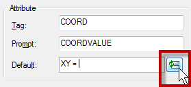
Let’s define our attribute. Give the attribute tag, prompt like below. In default field, type ‘X Y = ‘ then click insert field.
Change the field category to objects, and in field names, select object. Click select object button to define the object type. Select the circle, don’t select anything else!
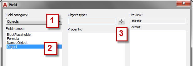
AutoCAD will list all available properties. Select center (or if you use point, select position). Because I only use it in 2D drawings, I don’t need it to display Z value. I turn it off. Change the format if necessary.Click OK.

Click OK again to close the define attribute dialog box. Place your attribute definition in the desired location.
Optional: Define Adjustable Leader
If you don’t want to have a leader on your coordinate label, you can skip this step.
I add a line that will be used as the leader.

Create the Block
Now we can define the block. Click create from ribbon, block panel.

Select all the objects, and define the center as an insertion point. Activate Open in Block Editor on the lower left of this dialog. We are going to add some ‘dynamic’ functionality. Click OK.
AutoCAD will show the edit attribute dialog. We don’t want to modify it as it is updated automatically. Just click OK.
Add the Control Grip
What we want to do is adding a grip control so that we can modify the text (and optionally leader) placement. In block authoring palette, activate the point parameter.
![]()
Now place it where you want the grip to appear.

Now activate the stretch action.
Select the point parameter, create the stretch frame like below, and select the line and attribute definition. [Enter] to end it.

Now we are done! Save this block and close block editor.
Using the Label
How can we use the label? Just insert the block, and click on the point you want to show the coordinate. After you have one of the blocks in your drawing, you can copy it and place it on several points you wanted.
Because we add a control grip, we can move the text and leader position!

Because we use a field, if you move your points, the value will be automatically updated! Very cool, isn’t it?
Why Attribute Definition? Why not Just Use Text?
You might ask this: why not just use text in a field? I know we can insert a field into a text, single or multiline. But it doesn’t work. You may want to try it by yourself.
Apparently, the field will consider the reference point always at 0,0,0 when you create a block. It works if you don’t create a block from them, but I believe you want to use it as reusable content, aren’t you?
Video Instruction
If you have problem, you can use this video as reference how to create and use the coordinate label block.


Edwin,
Thank you so much for this concept! We don’t use coordinate points on our drawings here (mostly architectural based drawings) so I changed things around a little and created an elevation mark that automatically updates level heights.
Julie
I’m glad that you find it useful and can implement it for other purpose :)
Hi , want to ask you about
if i want the attribute give me the heights such as heighhts of the window in elevation
What are the necessary steps for this ?
Hi Edwin,
this information is great! However, I have a question.
I received a drawing with hundreds of blocks with coordinates and need to export them to .txt file. Is there any way to name each one of them (eg. A01, A02, etc.), so I don’t have to manually re-write the exported file?
Thank you very much!
Eliska
Hi Eliska,
You can open the text file in Microsoft Excel and add the text there. Then you can save it to CSV or other text format. I think that is faster than modifying the drawing.
You can also modify the attributes. But depends on your block, the best workaround may vary.
Thank you, Edwin!
I have found easy way how to export attributes coordinates straight to .txt file with names of blocks already. Express tools -> Export attributes.
But the problem is, that I cannot see the block names in ACAD. Is there any way I can see name of the block in my .dwg?
Thank you very much!
You can activate block name in rollover tooltips. It’s the easiest way to check the block name. Here is how to change the rollover tooltips information: https://www.cad-notes.com/5-more-things-you-can-do-with-cui/
Or you can select the block and check the name in properties palette.
Edwin;
I am trying to do something similiar to what has been explained above. I would like to create a block that contains a tag and an embedded field attribute for the purpose of calculating surface area of paver fields for landscaping material extraction.
I can’t necessarily attached the wblock to an object as I would like to insert it into each drawing (unless the trick is to creat the block in my template) and multiple times for various pline shapes. I have created the block with the field attribute but can’t figure out how to be able to select the object it needs to calculate the surface area of for extraction.
Where am I going wrong here?
Thanks
Hi Kevin,
It’s not possible to use this block and fields for this purpose. You can’t select object after you place the block. Using LISP is the way to go.
I’m sorry I can’t be more helpful.
Dear Edwin.
That info is brilliant. Thank u a lot.
However I want to add another idea.
I do the same procedure in another order.
1.- Make the circle with the crossing lines as you do.
2.- I make a Block with that symbol.
3.- I open the Block in order to edit it.
4.- Only then I add the labels (as you do) and the leading line (the line connecting the symbol with the label)
5.- I add the “point” and so on (as you do in the chapter “Add the Control Grip”)
The difference is that I make the “labels” and the “leader line” after making the Block and inside the block editor.
The result is a little bit different: the label and the text are really attached to each other, so whenever I move them, they move together.
In your way I have to move the text and the leader separately.
Best Regards
Hi Alpla,
That’s interesting. Can you send me your block, so I can compare it? You can email it to edwin.prakoso@cad-notes.com
i want to convert x,y co-ordinates in excel into auto-cad.
so please give me suggest step by step.
Can this help you? Import X,Y Coordinates from Excel into AutoCAD
brilliant. got me out of a pickle
HI,
Edwin Prakoso
This is imran, I have one doubt, i have more then 400 Co-ordinates to provide coordinate's, for this i can't do 400 time copy paste (coordinate point block), is there any easy way to use measure cmnd or any other cmnd. to provide in small of time all coordinate's
thanks in advance
This is great thanks. I am trying to move the decimal point so that instead of it being after the 6th number I want it after the 6th, is this possible? thanks
HI,
This is Gandhi, I have one doubt, i have 50 Co-ordinates in excel if i appload the excel co-ordinates area marked in circle for single Query or lisp is it possible to do…