Dynamic block feature has opened many possibilities to enhance your AutoCAD libraries and your workflow. You can manage less objects in your library, and you can automate some process with it. In this first AutoCAD dynamic block tutorial, we will learn how to create an object with adjustable length. Many practices can use this process, but this time we will create a wall.
How long does it take to draw a simple floor plan with AutoCAD? Let’s say a typical rent office plan, not much walls to be drawn, plenty of open spaces. What if I say only need a few minutes? Includes annotation, door schedule, column schedule, and wall schedule? Drawing, not designing.
The secret is prepare your template, create some reusable content definitions, some customization, use the proper tools, then you are ready to rock! I will post several tutorials to prepare them, and will close this series with using all of them in creating our plan! In this topic, we will create a wall definition with dynamic block. You will see how dynamic block can speed up the design process.
Creating the Wall
Create a new file. Use acadiso.dwt as template. Sorry if you use imperial units, you might want to try use the same unit as I do, or use imperial by converting it.
Lets create 3 layers:
- A-Wall, set the color to red, lineweight to 1.5
- A-Wall-Structure, set the color to 9, lineweight to 0.09
- A-Wall-Pattern, set the color to 8, lineweight to 0.00
For your information, if you are not familiar with lineweight 0.00, setting it to 0.00 will plot the AutoCAD geometry using the lineweight as thin as your plotter can support.
Why we created 3 AutoCAD layers? We separate the structure and hatches so we can represent our AutoCAD drawing in different details. When we represent it in relatively large scale drawing, we can show all of them. But when we use very small scales, we will hide some details i our drawing. Yes, if you are Revit user, I’m imitating Revit detail level :)
Let’s start drawing our object. Activate layer A-Wall. Draw a rectangle with size 500×150 like below. Then draw rectangle 500×110 inside it on layer A-Wall-Pattern. After that, add a brick pattern on layer A-Wall-Structure. I use ANSI32 with scale 8 for this drawing. Make sure the pattern is associated!
Defining Block
After creating the wall geometry, let’s create a block from it.
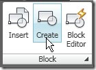
Select your wall as the block objects, and pick insertion point as shown below. Give your block name ‘brickwall’.
First step is done. You’ve created a reusable content for wall object, next we will add some intelligence to our object.
Add some Action
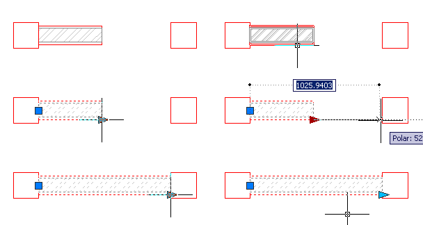
I want my wall can be stretched so it can fit wherever I place it. This is a very simple AutoCAD dynamic block, but I think it’s perfect practice if you never created a dynamic block. To add actions to your block, you have to open it in block editor.
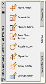
Select your block, right click, and select Block Editor from context menu. This will bring you to block editor interface. Let’s take a look to Block Authoring Palette.
It has three palette: parameters, actions, and parameter sets. Placing parameters is how you specify which parts of your objects to be references, and provide the information to actions you will add later.
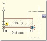
Open your parameter palette, then activate linear parameter. Place the linear parameter like below. It’s similar to placing dimension!
See the arrow on both side. We only need this wall stretched on the right side only, so we don’t need the left arrow. Select the left arrow, and delete it.
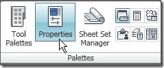
Open properties palette, it’s on view tab. Or you can simply type CH [enter] for command line freaks.
Select your parameter, change the distance label to ‘Length’.
We will use this label to create our wall schedule later. If you don’t change it, then you will have the default value ‘distance’ as column header.
Now we have finished placing our parameter. Now the block know we want to do something with the distance with the referenced points. There are several action can use linear parameter, but now we want to use stretch.
Open the action palette. Activate stretch action.
Select parameter:
Select the linear parameter you’ve placed before.
Specify parameter point to associate with action or enter [sTart point/Second point] <Second>:
Select the right point of our parameter, we want the wall stretched to this side.
Specify first corner of stretch frame or [CPolygon]:
This time you will have to define the stretch frame. Same with when you are doing stretch, only this time you predefine it.
Specify objects to stretch
We want all of our objects to stretch, so select them all.
Specify action location or [Multiplier/Offset]:
Place the action location. You can place it anywhere, it’s just a symbol. But the better place is near your action, so if anybody want to modify it later can find it easily.
Close your block editor. When AutoCAD ask you to save your block, save it. You are done!
Test your block, see if it works perfectly. stretch it to lengthen and shorten it.
Next, we will create another dynamic block. We will create multiple size of column inside a block. We will also use the column in our complete plan I promised you earlier.








If you choose to ever update the instructions you might want to give a little blirb about Hatching. Make sure your select the polyline used to create the inner rectangle. Or perhaps it will not update the hatch pattern when you stretch the block.
Rodney,
Thank you for sharing your experience. I tried both method (pick internal point and select object), both work fine here. But I believe your solution is the workaround if selecting internal point doesn’t work.
Thank you again for providing the solution.
I have problem to trim the wall for door and window place. It need to explode the wall first so i can trim the wall. Any solution how to put the door without trim the wall?
No. You can’t trim a block. But you can stretch this dynamic block to adjust the wall size and placement.
confusing, not well written CH command… best to just say edit the newly installed linear parameter with any dim editing command DDMODIFY is good
could follow your stretch instructions
could be much clearer…
hey, this is nice stuff but i wonder how we can use this block when turning the edges ? I mean i can’t connect two wall blocks at the edges ? So how will people overcome this issue ?
Unfortunately this block can’t work with corners. Here, we usually have columns at corners.
hi.. how come the hatch is not stretching? only the lines.
Aris,
You need to create hatch as associative hatch to make it work.
Edwin,
How come I can’t make the “Linear Grip” to be associated with column sides during the stretch? I tried everything but nothing works.
Regards,
Rusty Cao
Can you send me the file? I’ll try to check it when I can use my computer. Send it to info@cad-notes.com
Edwin,
File requested is sent to info@cad-notes.com for your perusal.
Thanks,
RCao
I have downloaded and tried your block.
Are you trying to have grips on both ends? As described in this article, we only make one grip, that’s why we deleted the left grip.
If you want to have them both, do not delete the grip after you placed it.
thank you so much. your steps are simply laid out and easy to grasp.
thanks for article. thats very good
i just fell i love with you with this article. Thanks so much !
This is a great article for any autocad user. It breaks everything down into easy to follow instructions for anyone to use. I highly recommend anyone having problems with AutoCad read this article as well as any others they can find.