In this Article...
If you already familiar with 3D modeling in AutoCAD, then you must be familiar with controlling coordinate system. The coordinate system you define will be a UCS (User Coordinate System). In 2D, there are many things that you can do by controlling coordinate system. In this article, we are going to discuss how to control it and why.
So Why Would We Need to Move/Rotate Our Coordinate?
- Working on angled coordinate/object.
UCS (user coordinate system) icon is showing you X axis and Y axis, an the origin. As you know, we input the point coordinate base on those axis. When we need to draw angled object in AutoCAD, in some cases it would be easier if we rotate the coordinate temporarily. - Working on local coordinate.
Surveyor often need to work with local coordinate, but they may not mess up with the global coordinate. In AutoCAD, we can consider World Coordinate System (WCS) as global coordinate and User Coordinate System (UCS) as local coordinate.
*What a coincidence. When I’m thinking about this post, Autodesk release a video on YouTube: tip to work on angled portion of your drawing.
How We Can Control the Coordinate System?
In the old days, we type UCS [enter] and choose the options. We still can do it now, but if you are not command line big fan, you may want to use the ribbon panel. Go to view tab, coordinates panel. All the options are here.
The tools on first row, are used to move, save, or reset coordinate system to world coordinate system (WCS).
On the second row, you can use the tools to rotate AutoCAD coordinate system using coordinate axis. Except the last one, the one with the light bulb is for turning UCS icon on or off.
The last row, there are tools that you can use to quickly aligned the coordinate by view, object, or picking 3 points.
Try to see AutoCAD extended tool tip to see more explanation.
Examples
Aligned Objects
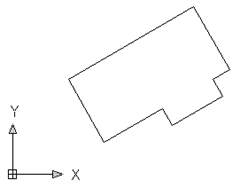
Let us see the building footprint below.
Let’s say we need to draw the interior, parking lot and more objects to complete the AutoCAD drawing. It would be easier to rotate the coordinate system to complete the job. In this example, I use object and pick a line in the drawing.
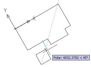
As you can see, the UCS icon is now moved and aligned to the top most line (I pick that line).
Now when we create rectangle, linear dimensions, etc it will be aligned to the current UCS orientation. And don’t forget, ortho mode and polar tracking also using the XY axis! Try to create linear dimension and see how it works.
Using SNAPANG
You can also use SNAPANG to rotate the cursor. It is very useful if you want to create line with specific angle. By rotating the cursor, you only need to type the line length.
However, SNAPANG doesn’t change the coordinate after you rotate the cursor. When you type 5,0 coordinate as next point, it will be created using current UCS. Not aligned to the cursor.
Thank you to Mark Loomis, Chad and Craig Black for bringing this up.
Rotating View
Still find it difficult? Many of us prefer to work with the object aligned to our screen. No problem.
Now type PLAN at command line then press enter.
In the command option, choose Current UCS.
Now you can see the viewport is now align to your new UCS, which is parallel to your screen. It’s much easier to work now, isn’t it?
Using Local Coordinates
Sometimes you need to draw or annotate relative to local coordinate and not to world coordinate. You surveyors should familiar with this. If you are in manufacturing industry, you probably need to annotate part/assembly coordinates, or holes coordinates. In Architecture drawing, you may need to annotate the elevation view.
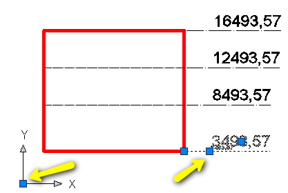
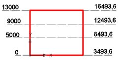
This example, shows a rough elevation view (yes it’s bad and lazy drawing, I know), but the elevation level is not showing correctly. The bottom red line should be at 0,00 elevation. It’s because ordinate dimension use 0,0 as origin. We need to move the origin before create the ordinate dimension.
So after we restore the UCS to World coordinate, the dimension will use the world coordinate value? Nope. See below. The right dimensions was created in word coordinate. The left dimensions on local coordinate. The value never changed even we move the UCS around to new places.
So how do you use UCS to increase drawing productivity? Is there any other tips you want to share with us?


Hi,
could you help me for adjust the drawing for getting the right coordinates.
means how i can make sure my drawing is right for take any coordinates.
because i don’t know the method can you tell me from the begning what we have to day when drawing is open.
this article is so informative and useful for me .
Hi. Can I put the snapang command in the toolbar? I do not see it in CUI. Do I have to write it all the time? It is a bit annoying writing this command 1000 times per day :)
Hope you can help me…
Best regards
Hello
I have quit an annoying issue.
I use quite often the UCS rotate function by object.
Now I have a drawing in which I can NOT draw according to the new UCS.
example:
I have a building oriented by 7°. So to draw in parallell I use to set my Object UCS on a line of the building.
My Crosshair Lines seem to be turned/adapted by 7°. So far so good.
As I start drawing a line the Crosshair Lines become ‘normal’ again and the line is not drawn by 7°
Afterward the Crosshair Lines turn to 7° again.
Help!!!
Is this some variable?
in a new drawing everything works just fine…
That is strange. I’ve never seen this behavior before.
But my guess it could be UCSVP variable. Try to change it to 0 and see if it helps.
hi sir i want to know how i can convert the drawing layout coordinates. how i take coordinates from autocad for layout beacuse i have drawing that i9s not set at layout coordinates how i can stet?
Om Erwin,
Mau tanya. Saya attach reference Raster. Pas mau di plot, saya rotate ucs supaya semua masuk ke bidang kertas. Tetapi raster image nya kok cuma clip saja, enggak ada imagenya, Bagaimana supaya image nya tetap[ ada ya?
Thanks
Irwan Joe
hi sir, i ask how to print the autocad drawing?
Mary,
Have you tried this guide? https://www.cad-notes.com/5-steps-preparing-your-autocad-plot/
please show the correction of coordinate
SNAPANG also works well in this case.
Thank you Mark!
I should include that. I’ll update this post later!
hi
pictures did not show ,please correct them
thank you
Hi, could you please try again?
thank you Mr Edwin for sharing great tips