Revit creates views automatically. You don’t need to create plans, elevation, and section views manually. Revit also generates the patterns automatically.
There are two locations where the patterns can appear: on the surface of the elements (no. 1, 2, and 3 below) or when we cut the elements (no. 4).
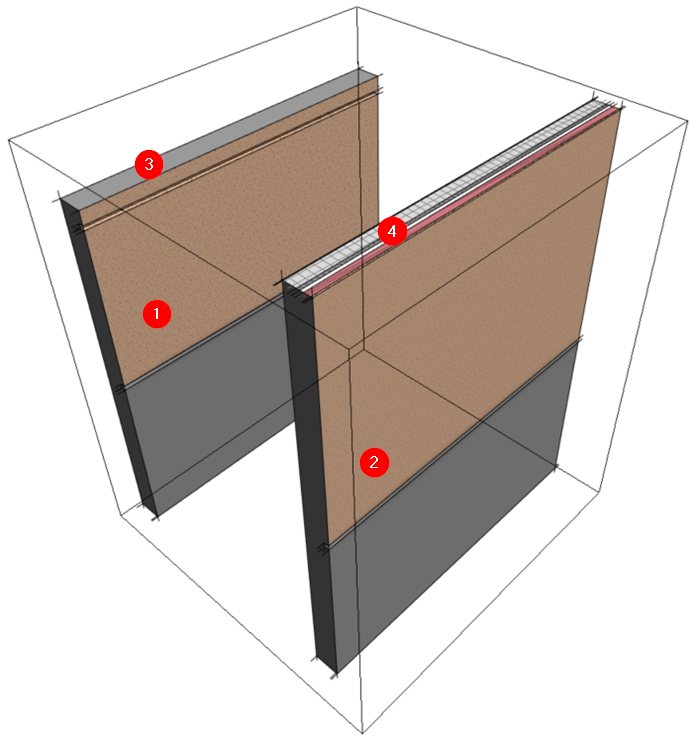
No. 1 and 2 are apparent. The patterns appear on the surface of the wall. Using this type of pattern, you can show the surface finish for a brick or a textured wall.
No. 3 shows the top of the wall. The wall is lower than the section box, so it’s not cut.
No. 4 is the same type of wall but higher than the section box. The section box cuts the wall, and Revit shows the materials that form the wall.
How can we set these different patterns?
Editing Revit Material with the Material Browser
We can define patterns in the Material Browser. You can open it by clicking the Manage tab> Settings panel> Materials icon.

Select a material, then open the Graphics tab. You can see the patterns for this material. There are two types of patterns: surface pattern and cut pattern.
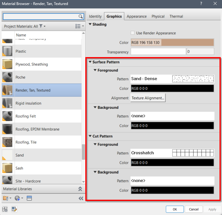
Surface Pattern
The surface pattern is straightforward: Revit will show the surface pattern on the element’s surface. Refer to no.1, 2, and 3 on the wall image.
The pattern on the surface can represent the actual element pattern (i.e., wall tiles, brick patterns, etc) or as an annotation. That is why you can use both model and drafting patterns for the surface pattern.
Cut Pattern
As the name implies, Revit shows the cut pattern when an element is cut, like no. 4 on the wall image. It also applies to sections, plans, and other Revit views.
The cut pattern is for annotations. That is why you can only use drafting patterns for cut patterns.
Revit creates views by cutting the model. A floor plan is produced by cutting the model at the cut plane.
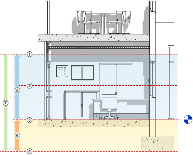
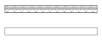
The image below shows two walls of the same type. The first wall is higher than the cut plane, and the second is lower. You can see that the first wall is cut and shows the cut pattern, but the second wall is not.
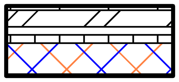
Foreground and Background Pattern
Revit has foreground and background options. What is the difference?
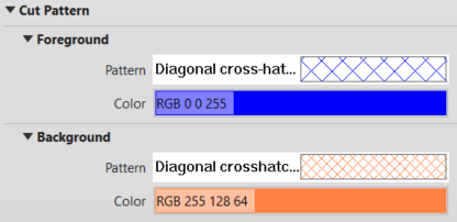
The foreground pattern always shows above the background pattern. It is helpful if you want to show a dense background pattern but want the foreground pattern always visible.
To Sum Up
Revit creates views automatically. Revit automatically shows all elements in your file in a related view, including the patterns as annotations or as actual element patterns.
You must define the elements’ properties to ensure they work correctly, including the materials’ patterns.


