I had this question several times: can we automatically label our coordinate in AutoCAD? If you are a Civil3D user, then you most likely will suggest them to use C3D. But can AutoCAD do it? YES!
I saw many people use AutoLISP to do that task. It works great. But sometimes you may want to have your labeling symbol and format. So, why not using field?
Creating a reference object
First, we need to create an object as a reference point. It can be a point, a circle, or any symbol you want it to appear. I use this symbol.

I prefer to use point or circle. We can easily use the point position or circle center.
Creating an Attribute Definition
After we have the reference object, we need to define an attribute definition. You can activate it by clicking it on your ribbon, home tab, block panel.

Or simply type ATTDEF then [enter].
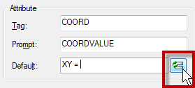
Let’s define our attribute. Give the attribute tag, prompt like below. In default field, type ‘X Y = ‘ then click insert field.
Change the field category to objects, and in field names, select object. Click select object button to define the object type. Select the circle, don’t select anything else!
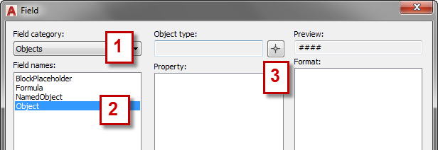
AutoCAD will list all available properties. Select center (or if you use point, select position). Because I only use it in 2D drawings, I don’t need it to display Z value. I turn it off. Change the format if necessary.Click OK.

Click OK again to close the define attribute dialog box. Place your attribute definition in the desired location.
Optional: Define Adjustable Leader
If you don’t want to have a leader on your coordinate label, you can skip this step.
I add a line that will be used as the leader.

Create the Block
Now we can define the block. Click create from ribbon, block panel.

Select all the objects, and define the center as an insertion point. Activate Open in Block Editor on the lower left of this dialog. We are going to add some ‘dynamic’ functionality. Click OK.
AutoCAD will show the edit attribute dialog. We don’t want to modify it as it is updated automatically. Just click OK.
Add the Control Grip
What we want to do is adding a grip control so that we can modify the text (and optionally leader) placement. In block authoring palette, activate the point parameter.
![]()
Now place it where you want the grip to appear.

Now activate the stretch action.
Select the point parameter, create the stretch frame like below, and select the line and attribute definition. [Enter] to end it.

Now we are done! Save this block and close block editor.
Using the Label
How can we use the label? Just insert the block, and click on the point you want to show the coordinate. After you have one of the blocks in your drawing, you can copy it and place it on several points you wanted.
Because we add a control grip, we can move the text and leader position!

Because we use a field, if you move your points, the value will be automatically updated! Very cool, isn’t it?
Why Attribute Definition? Why not Just Use Text?
You might ask this: why not just use text in a field? I know we can insert a field into a text, single or multiline. But it doesn’t work. You may want to try it by yourself.
Apparently, the field will consider the reference point always at 0,0,0 when you create a block. It works if you don’t create a block from them, but I believe you want to use it as reusable content, aren’t you?
Video Instruction
If you have problem, you can use this video as reference how to create and use the coordinate label block.


Could you post example file again?
Dear Edwin,
Thanks a lot for the Tip,
Cant I see(place) coordinate as a text on screen.
Hello Edwin, can i ask you a question? How can i see all the E & N coordinates on a drawing in Autocad? I’am a graduate who is working as a assistant engineer. I can manually calculate the E&N, but i would also like to learn how to work and compare my calculations with those on Autocad.
Thanks
Doing something very similar with a level mark that takes the Y coordinate as the verical height of a building. The Problem I have is: Drawing is in mm but the level needs to be in m (display “4.300”, not “4300”) Any ideas?
I am using Blockplaceholder/ Position/ Y and Precision 0. The issue is that it will not allow a conversion factor (in additional formatting). If I could add one (say 0.001) the problem would be fixed.
I have just found a solution to a problem, at work. It is to use AutoCAD to get a result. It is 16 years since using ACAD, and the rust has really set in. I have a coordinated survey and need to plot a drawing with the XYZ coordinates at each point. The company has AutoCAD LT 2010, which they installed. I found on another website a lsp listing, but ACAD does not seem to recognise this.
I have tried the How to: Label Coordinate in AutoCAD, on your site, but cannot get it to work, I got fairly close, but all it did was put the same coordinates at each point.
Is there anyway you can email a block to me which I could import into my drawing. I have wasted hours on this and getting nowhere. Why the hell ACAD, who allow for dimensions just did not include this as a facility!
Regards Philip
Hi Philip,
You can download the block here: http://1drv.ms/1IWzQHM
HEY MAN YOU ARE THE MAN. I HAVE BEEN LOOKING FOR THIS FOR A LONG TIME.
I’m glad that it helps! Share it with your friends, will you? They might like it too :)
Hello sir Edwin,
I can’t download the file, it say’s that ” this link doesn’t work anymore, contact the owner” can i have the permission to download your file sir?
Thanks in advance.
hi
I have a problem, i need to set a specific block attribute coordinates.
I’m afraid to change its settings because it is supposed to work/Read on GIS System
tried lisp log and attribute definition it causes the block to change.
So far, what greeted me was your lisp coordinates.
Then i Changed the Mtext to my specific block attribute.
About 20 to 40 blocks in drawing
Hope you can help me with this.
Thank you so much for your post. You made my job easier. Thaks and greetings from Mexico :D
I’m glad that it helps!
Hi
I have a set of blocks, defined like you did, with a text attribute indicating a z value for each of the block (the base geometry is a point).
Is there a way I could globaly set these points at the Z position indicated in the attribute field of each one of them?
Thanks for your help and attention
Suit
When i copy and move the block the coordinates stay as the original, is there a way to make these update as the block is moved / relocated?
Not sure what you want to achieve. We don’t usually move the block base point. It’s better for you to move the blocks in your drawing.
I have the same problem as above. If I insert the block, it displays the correct coordinates, but if I move the block or if I copy the block, the coordinates don’t adjust to the new location.
Thanks!
The value will be updated when you REGEN, save or plot the drawing. Try one of those and see if the value change.